Basic Electronics for Audio Part 2, Series or Parallel
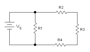
When you begin electronics classes, you will be faced with the most basic of circuit analysis, series and parallel resistor networks. Using Ohm’s law we can determine just how much voltage can be seen and current is flowing through each part of the circuit. This basic analysis is applicable to audio for a wide variety of tasks from determining what load a power amplifier receives when hooking up multiple speakers, to just how many stomp boxes your guitar can drive before losing most of it’s output and sounding like crap. It is also the fundamental theory behind how a volume knob works.
Series
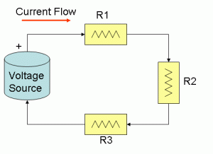
Hooking up loads in series is like creating a chain. The input and output of the chain only touches one of the links, with each link connected to each other in the middle. Each load resistance simply adds to the total as you go down the chain, creating the simplest formula for determining the total resistance:
R total = R1+R2+R3…
As for the current, there is only one path for the electrons to flow through, so each part of the load see exactly the same current through it. This is easy to calculate with Ohm’s law as I = V / R total. Once you have the current flow, you can use Ohm’s law again to predict just how much voltage will be seen across any of the individual loads in the chain by simply multiplying that current by the resistance of any single load.
Parallel
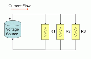
To visualize a parallel connection, visualize a simple power strip. Each plug is connected to the same leads going to the wall, so everything plugged in has access to the same wall voltage as if it was plugged in directly to the wall itself. In this case, the voltage on each of the loads remains constant and therefore the current is split among the loads according to each of their resistances. The total resistance is a bit more complicated to calculate than the series circuit, but can be found with Ohm’s law just like everything else.
- Each load has it’s own current flow, calculated by I=V/R.
- Each current flow adds together so a total current flow is calculated by I total = I1+I2+I3…
- The final load resistance can then be found by taking that total current and the input voltage back into Ohm’s Law again, R total = V/I total
There are a couple different methods for calculating total resistance of a parallel network without the need for voltage or current, the simplest of which is:
R total = 1 / (1 / R1 + 1 / R2 + 1 / R3…)
Also, if you happen to be using all the same resistances in your network, such as a group of 8 Ohm speakers, the total resistance is simply the resistance of one of the loads divided by the number of loads in the network. So a pair of 8 Ohm speakers in parallel is a 4 Ohm load, add another and you get 8/3 or 2.67 Ohms.
Mixed Networks
You may find yourself looking at a circuit with both series and parallel connections inside it. In this case you’ll want to identify and attack the parallel sections first, simplifying the whole circuit into a simple series network. Each block can then be quantified individually. At this point I have to throw another definition at you, the electrical Node. A node is simply a single conductor that may have any number of connections on it. The conductor itself is treated as an ideal conductor with 0 or negligible resistance. This means it will pass current transparently, and will be at the same voltage at any point on that node. In a real circuit this can be a trace on a circuit board, a group of wires, or even the metal chassis itself. In order to determine what type of circuit you’re dealing with, you’ll need to identify the nodes. In schematic drawings, the nodes are any straight line.
- All parallel circuits must share nodes on BOTH sides of each load
- All Series circuits share a node in between each load, but never on both sides
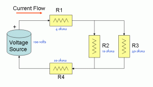
In this circuit, resistors R2 and R3 are in parallel, since they share nodes on both ends. Resistors R1 and R4 are both in series with each other, and the R2/R3 combination. For this example, lets say we’re inputting 100V into the circuit, we can calculate everything using the values in the figure. Let’s figure out how much power is applied to the resistor R2.
- First, we’ll figure out what the R2 and R3 network resistance is. Using the formula R total = 1/(1/10 + 1/40) we get 8 Ohms.
- Adding in the series resistance of R1 and R4 we get 8 + 4 (R1) + 20 (R4) for 32 Ohms
- With 100V input, we get a current of 100 / 32 or 3.125 Amps
- At this point we know that 3.125 Amps is flowing through the parallel combination of R2 and R3, we need to know the voltage across just that portion to continue. That can be found by using the parallel resistance we already calculated and the known current, so the voltage is 3.125 Amps * 8 Ohms or 25 Volts.
- We can then skip to the power formula for voltage and resistance (you read part 1 right?) Power = (25 Volts)^2 / 10 Ohms or 62.5 Watts
So what do I do with this then?
I admit, calculating this stuff on paper is a little less than fun for most people. So the real use of this knowledge becomes actually applying this to a situation in your studio or another audio setup. The first thing you may run into that can use these calculations will be setting up your speakers.
Speaker Network Calculations
Listed on any amplifier’s specification sheet will be the minimum load resistance the amp can drive without self destructing. If you want to hook up multiple speakers to that amplifier, you better know what load you’re ending up with in order to keep that amp working. In live audio, speakers typically have a pair of jacks wired in parallel so you can keep connecting speakers at the end of the line. You need to be aware that you are making parallel connections at that point and the resistance will be divided by the total number of speakers. Typically professional audio speakers are all 8 ohms so the calculation is simple division, but for passive studio monitors or consumer home and automotive audio, the speakers can have a variety of impedances.
Lets say you have a pair of 4 Ohm speakers and a single 8 Ohm speaker that you want to drive off a single amplifier channel that is rated to drive a minimum of 4 Ohms.
- Can you connect them all in parallel? No… in parallel you end up with 1 / (1/4 + 1/4 + 1/8) or 1.6 Ohms… way too low for that amplifier.
- How about all in series? That will give you 4+4+8 or 16 Ohms, which of course the amplifier will drive just fine, but you won’t get much power because the amp as a finite limit on output voltage and since power is divided by resistance in the formula, you’ll have only 25% of the available power in a 16 Ohm load as you would a 4 Ohm load.
- How about putting the two 4 Ohm speakers in series, for a 8 Ohm load, then paralleling them with the other 8 Ohm speaker…. voila! That ends up right at the 4 Ohm total load the amplifier is rated for, giving you maximum power and utilizing all your available speakers.
A note about speakers in series
For the purposes of this article, we’re dealing with simple resistance. In the real world however, speakers have what is called a complex impedance, which results in a great deal of variance in resistance based on what frequency you’re putting in. This causes problems for series circuits as the voltage and therefore power going to each speaker is going to depend on the impedance ratios, and if you’re using different speakers in series they will dramatically affect each others frequency response. The general rule is this, use only parallel connections if you can, and only put identical speakers in series. Using identical speakers ensure that the impedance variations are roughly equivalent, and therefore the resistance ratios remain the same in the circuit and the frequency response will not be affected.
Voltage Divider
The most basic use for a series circuit is the simple passive volume control or attenuator. You can create and use one of these in any situation a high signal level needs to be pumped into something that can’t handle it. For example, what if the only signal available to you is at a speaker, and all you have is a microphone input? You’re going to need some method of killing off that voltage to knock it down to a reasonable level for your use.
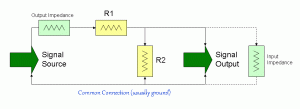
With a simple voltage divider we can calculate the reduction by simply finding the ratio of the output resistor over the sum of both resistors. So in this drawing, a 10K Ohm R1 and a 1K Ohm R2 will get you a reduction of R2 / (R1+ R2) which in our example is 1K / 11K or 0.09. That means if you put in 10V on the input, 0.9V will appear on the output.
That’s the theory, however in reality there’s a couple other values that need to be considered. The input to the circuit will have some amount of output impedance. This looks like an additional series resistor to the circuit. Fortunately, active outputs like those found on the back of your stereo, the output of a pre-amp or amplifier all have very low output impedances and this can generally be neglected as it’s affect on the output will not be noticeable. On the other end, anything you connect the output of your voltage divider to will also have an Input Impedance. This will look like an additional resistor in parallel with your output resistor and cause the circuit to reduce the voltage a bit more than calculated. Using the same values, lets say we’re connecting this to a pre-amp that has a 1K Ohm input impedance. That will be in parallel with the output 1K Ohm resistor for a total resistance of 500 Ohms. This then goes into the divider formula as 500 Ohms / (500 Ohms + 10K Ohms) or 0.047. That’s pretty much twice the reduction planned, a heck of a difference yes? The voltage divider itself works on the ratios between the resistors so a 1K R1 and a 100 Ohm R2 will get you exactly the same reduction. Using the same 500 Ohm input impedance the parallel value becomes 83.3 Ohms for a total network reduction of 83.3 / (1K + 83.3) or 0.076… a whole lot closer to the planned 0.09 eh?
Basically planning a voltage divider attenuator comes down to value choice. You need your output resistor to be at most 1/10th the input impedance of what you’re connecting it to to avoid it having an appreciable affect on the reduction. You also want to make sure the total network resistance is greater than the load whatever you’re driving it with can handle. So don’t pick a 1 Ohm and 10 Ohm resistor and expect a pre-amp to drive a 11 Ohm load.
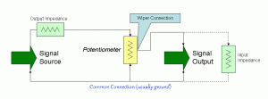
The Volume control creates this voltage divider in a single, adjustable device. This is called a Potentiometer
The arrow is called the wiper and created the node in between your series resistors. As you move the wiper, one side is reduced in resistance while the other is increased, allowing you to change the voltage divider on the fly and giving you control over the output voltage. When picking a potentiometer value, you have a little more leeway than a fixed voltage divider. Remember the circuit you’re driving it with will see at most the value of the potentiometer, and at least that value in parallel with the input impedance of whatever you have it’s output connected to. Ensure the potentiometer is a high enough value to not overload the circuit driving it, but also in the neighborhood of the circuit you’re outputting to.
Is that it?
Well, there you have it. You now know the basics about series and parallel circuits and can use that knowledge to confidently predict the load on an amplifier given a set of speakers, or create yourself a fixed attenuator.

Good facts, thanks a ton.
Amazing details. I’ve bookmarked this web site.