Creating a Woofer Kick Drum Microphone
Concept
Both speakers and microphones share the same concept, they are built using a linear motor that transfers electricity into motion, or motion into electricity.
The idea of using a woofer speaker to capture the really low frequencies produced by a acoustic kick drum is not new, and has been employed in studios for decades. The output of these microphones is very specific to super low frequencies and can add a nice subsonic thump to your recordings that typical microphones simply cannot produce. Retail version of this concept can be found, but are quite a bit more expensive than the do it yourself project. For example the Yamaha version will set you back over $300, while the parts to build your own will cost less than $50.
This article will step you through the selection of a driver, the wiring required to make it work, and a bit about the use of the microphone in a mix.
Driver Choice
There are quite a few parts suppliers out there that sell bare woofers, including Radio Shack. Personally I have used Parts Express many time due to their close proximity and fast shipping to my location and their variety of stock.
The woofer microphone will be used in a free air, open basket arrangement, so there are a few specifications to watch out for while choosing a driver.
- Size – A 6.5″ driver is plenty large for this purpose but any size will work.
- Free Air Resonance – This is typically denoted Fs and will determine where the mic is most sensitive. This is kind of a personal preference, but the range should be between 30 and 50Hz. A 30 Hz signal will be felt in your pant legs while a 50Hz signal will punch you in the chest.
- The remainder of the specifications will affect the microphone output and impart some character to the output. These will be somewhat compensatable with EQ and dynamics processing.
Wiring the Woofer
The woofer will have two leads, simply a positive and negative terminal determined by which voltage is produced as the woofer cone is moved in or out of the basket. These need to be wired to an XLR cable to allow a connection to your mixer of choice. In addition to the connection to the cable, the signal needs to be reduced to avoid overloading the input of your mixer, you would be surprised just how much voltage can be produced by these things.
In order to easily connect the woofer to your mixer, you will need a short lead from the woofer with a male XLR connector wired on.

The XLR connector needs to be wired correctly if order to interface with your mixer.

From left to right you have the ground, positive, and negative terminals. The ground pin will be soldered to the basket of the woofer to provide shielding of the whole assembly while the positive and negative terminals will be reversed and connected to the woofer.
Why reversed? Because the woofer will be facing the rear of the kick drum so as the cone moves in, a positive signal needs to be generated.
A voltage divider will need to be created to reduce the output of the woofer. This is simply two resisters wired in series between the terminals with the output taken right in between them. A 10:1 ratio drops 20dB off the signal and should keep you from overloading most mixer inputs. The impedances we’re dealing with are low, and general electronics design should have a low impedance driving a high impedance to avoid load losses. Since the woofer is already 10 ohms or less, and the mixer input is typically 600 ohms or more, we have a lot of room to choose values. A 1K ohm resister in series with a 100 ohm resister with the signal taken from the 100 ohm resister will work fine. In reality, the signal reduction will be a little greater than 20dB due to the parallel load of the 600 ohm mixer input, but you will still have no trouble getting the signal levels up for mixing and recording.

Here you see that I have taken the shield of the cable and soldered it to the eyelet on the woofer where the connectors are attached to the basket. That will serve as a strain relief so when the cable gets pulled, it will not break the small wires or resistor network.

Once the XLR lead is soldered on the woofer, you’re ready for the fun part, mounting and using your woofer mic!
Mounting
The woofer microphone is intended to be used within a few inches of the resonant head of a kick drum. This poses a bit of a mounting challenge and requires a bit of creativity to overcome.

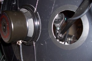
I used a bit of steel wire to hang the woofer from the mounting hardware. This is less than ideal for a portable live sound situation but works fine in a studio with a stationary drum kit.

Here you can see the regular kick drum microphone positioned inside the kick to capture the attack and presence of the drum.
Mixing with a woofer microphone
The output of a woofer microphone requires a little getting used to in order to fit it in your mix and not accidentally kill speakers with the tremendous low frequency output this thing can produce. First, keep in mind the output is really, really deep. If you’re using small woofer near field monitors you won’t even hear the track and may be tempted to raise the level until you do.
Don’t over do it… when you move the mix to a system with a subwoofer, you’ll be blasted out of your chair. That is if you have managed to not see the tiny plume of smoke indicating your little monitor woofers are overloaded and gone to the speaker stand in the sky.
Keep the level of the woofer track low, and a second kick track with a regular microphone is absolutely necessary to get the attack and presence you need to hear the kick in the mix. Get the regular mic track where you want it, and bring the woofer output up behind it. Use a spectrum analyzer like Voxengo SPAN to see the low frequency levels in your mix if you don’t have monitoring capable of producing it in your room.
As with any mix… try your output on as many systems and speakers you can and adjust accordingly!
I like your web site. Pleasant to read about anything that’s drumming related, what’ve you got coming next?
Does it matter what ohms the speaker is that is being used (2ohm 4ohm 8ohm ect)?
The speaker impedance doesn’t really matter much actually, though the low impedance drivers (2 or 4 ohm) will have lower signal level outputs. That may not be a bad thing though, as the levels coming out of these things are really hot anyway.
Once you put it together it’s a good idea to try it out with your mixer / recording interface and see what the signal levels are, then adjust the voltage divider values as necessary.
Hey, good article, I just put your site in my favourites so I can keep following it. Keep it up.
Just wish to say your article is as astonishing. The clearness to your post is just nice and i can assume you are a professional in this subject. Well along with your permission let me to take hold of your RSS feed to stay updated with impending post. Thank you 1,000,000 and please keep up the gratifying work.
Is the 1K ohm resister solder to the speaker negative terminal ???
Yes it is, the polarity is intentionally reversed. A microphone will typically produce a positive signal output when a positive pressure wave of sound hits it. Speakers are designed to produce that pressure wave instead of receive it, so their electrical polarity is opposite of what a microphone would be.
Hi. One question – if phantom power is applied to the woofer mic will this cause any problems?
Nope, phantom power does not cause problems. The 48V is applied between the ground connection and the negative signal pin. The woofer coil is between the + and – pins, so there’s no path for that 48V to cause an issue.
Make sure you keep the resistor network tight and don’t let any stray wires hit the metal of the woofer basket, or you could short out that phantom power.