The JPG – A vintage inspired speaker
I’ve wanted to get this design on paper for a while. My dad did a pair of large 15″ 3 ways when he was young, and I grew up with them as inspiration to get into speaker building my whole life. They were designed with tools at the time, which were basically text book 2nd order crossovers and adjustable L-Pads on the tweeter and mid to bring the levels in. I have no idea what drivers he used, I do know that it was a 15″ woofer, and a paper dome mid and tweeter. The design was set on it’s side, with vertically oriented mid and tweeter next to the woofer. He originally did it ported, but didn’t like the sound so he sealed them up. I’m pretty sure he didn’t have the correct port calculations though, based on us building boxes later in my teens.
He passed away in 2015, just before I learned all these sweet DIY crossover design tools. So this design is a tribute to his work in the 70’s, I’ll call the JPG Tribute. Also, since I don’t have a purpose or place for speakers this size the design will remain theoretical for me.
Design Process
To work on this design theoretically, I chose all Dayton drivers due to their availability of consistent and good quality measurement data. I designed using their FRD / ZMA files, processed with response modeler to add baffle and diffraction signatures processed to minimum phase. The acoustic offsets, particularly the Z offset is guestimated, so some minor adjustments are likely if these end up in real life by anyone.
Drivers
- DC380-8 15″ woofer
- RS52FN-8 dome mid
- RST28F-4 tweeter
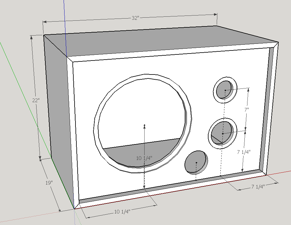
Design Aesthetic
The originals had an inset baffle with a classic tweed fabric covered grill, so I’m doing that here as well. He actually used particle board, and stained and poly coated it for a deep color with the fine chips of the particle board visible through the stain. Looked pretty good, but this would be nice in a BB ply as well.
Woofer Alignment
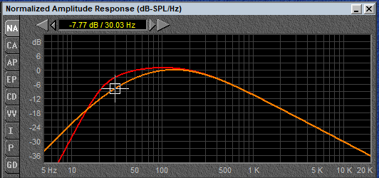
The volume was dictated by my estimated size of the originals, a solid 5.8 cu ft. That puts a a vented alignment tuned to 23Hz with a 4″ x 7.7″ port in line for the DC380-8 woofer with an F3 of 30Hz. Sealing the port yields a low box Q of 0.48 with an F3 of 52.
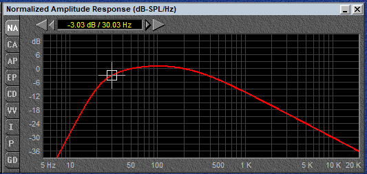
In my opinion, either would work well. The DC380-8 does run out of Xmax a bit though, so a full 100W and 110dB of output will get you some over-exertion.
Crossover Design
All FRD files were processed with their position on the baffle, though the inset was not considered. I played with 2nd order electrical filters, targeting around an LR4 acoustic roll off. Didn’t quite nail it, since this works without an inverted mid as you would expect for LR4. Regardless this shows a sim of within +- 3dB with a bit of a reverse null, though not super deep.
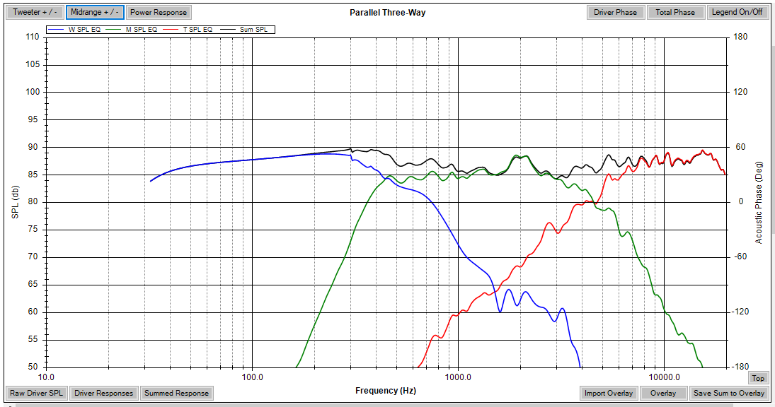
Crossover points landed around 600Hz and 4.5kHz.
For the woofer, I saw a large breakup peak in the response that was tamed with a parallel notch cap on the woofer coil. Since the notch cap ended up fairly large at 2uF, I added some series resistance to avoid very low capacitive loads at supersonic frequencies.
With the sensitivity of the woofer, I didn’t have to pad the mid and tweeter too hard so the mid has just a little series resistance both before and after the network.
Likewise, the tweeter is a simple 2nd order with a single pad resistor.
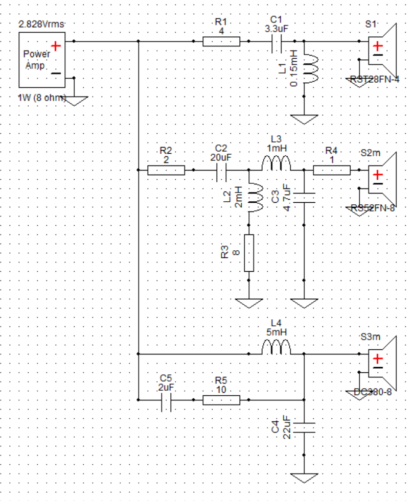
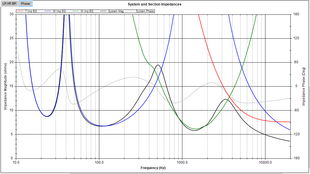
The system impedance ends up approximately 8 ohm nominal, but dips into 4 ohm territory as you reach high frequencies. This shouldn’t be a big deal for amplifiers though, as the vast majority of your power is spent down low.
Orientation and Dispersion
This design is intended to lay on it’s side, due to the way the mid and tweeter are arranged. Generally, the best practice is to make sure your dispersion is even across the horizontal plane, as your listening positions may vary across the room but will generally be at about the same height. Having drivers spaced horizontally introduces comb filtering across the horizontal plan as the distance between the drivers and your ears changes, causing phase differences to cancel and reinforce different frequencies.
The simulation application I’m using WinPCD estimates the dispersion of the speaker using the physical dimensions of the relative speaker locations, as well as estimating the directivity of the speakers using their radiating dimensions.
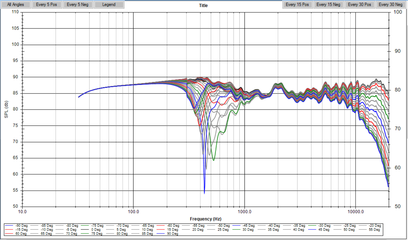
This speaker shows this lobing response effect at the crossover point between the mid and woofer, but since the tweeter and mid are vertically aligned, their transition remains smooth across the horizontal plane.
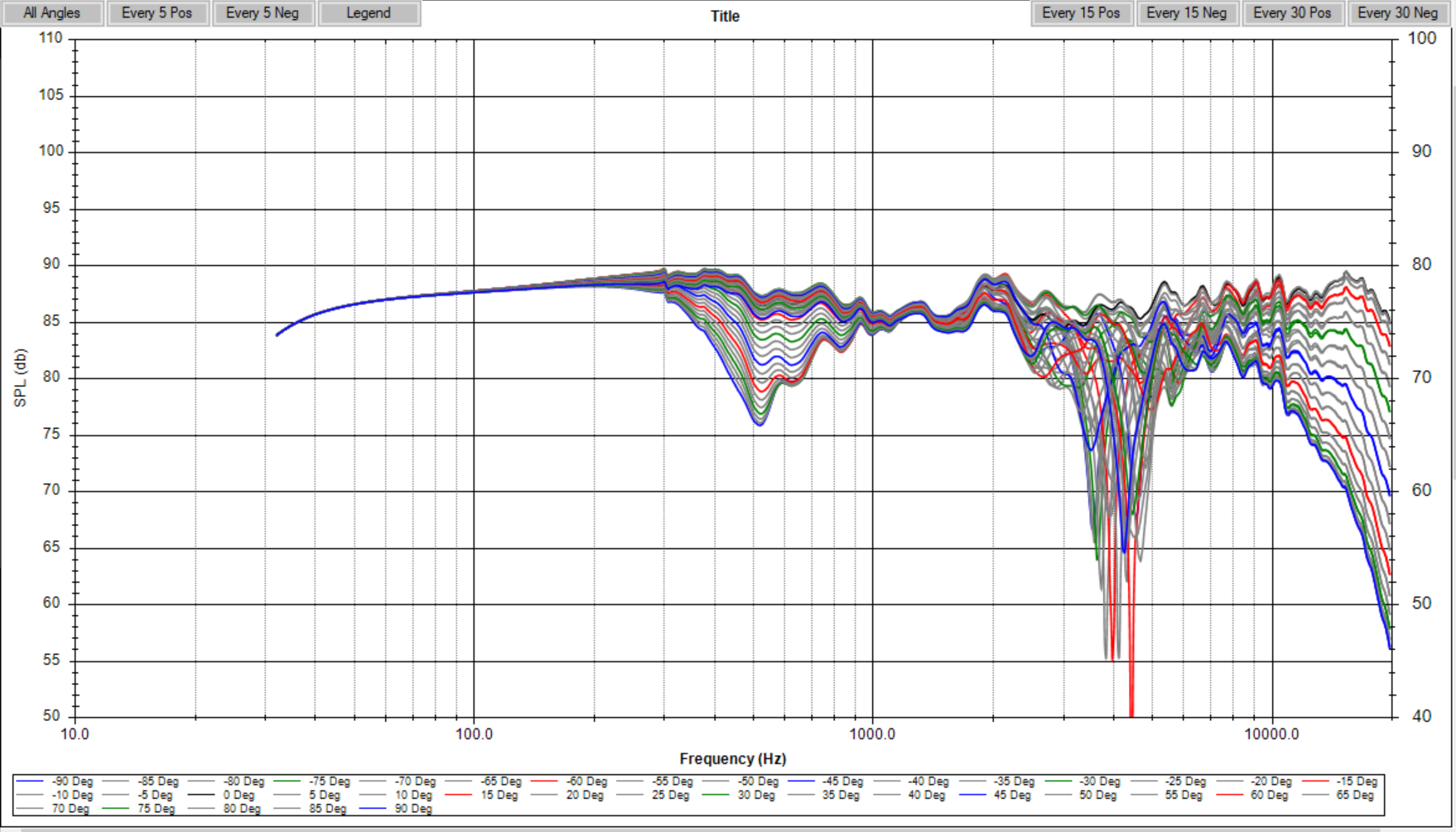
In the vertical plane, the lobing problems show up at the mid to tweeter crossover point, while the woofer to mid transition is a bit better. Our ears are generally a bit less sensitive to these things in the lower frequencies than the upper mid-range, so it is recommended to keep this speaker on its side as designed.
Conclusion
If my dad were around I think he’d dig these suckers. Sadly, my parents were living in condo’s later in life so the originals had to go long ago due to the space needed to place them, and the irritation that resulted with the neighbors due to a pair of rocking 15″ woofers.
Even though I won’t be building these, the design is here for anyone to give it a shot. Thanks for checking it out!
All Images


