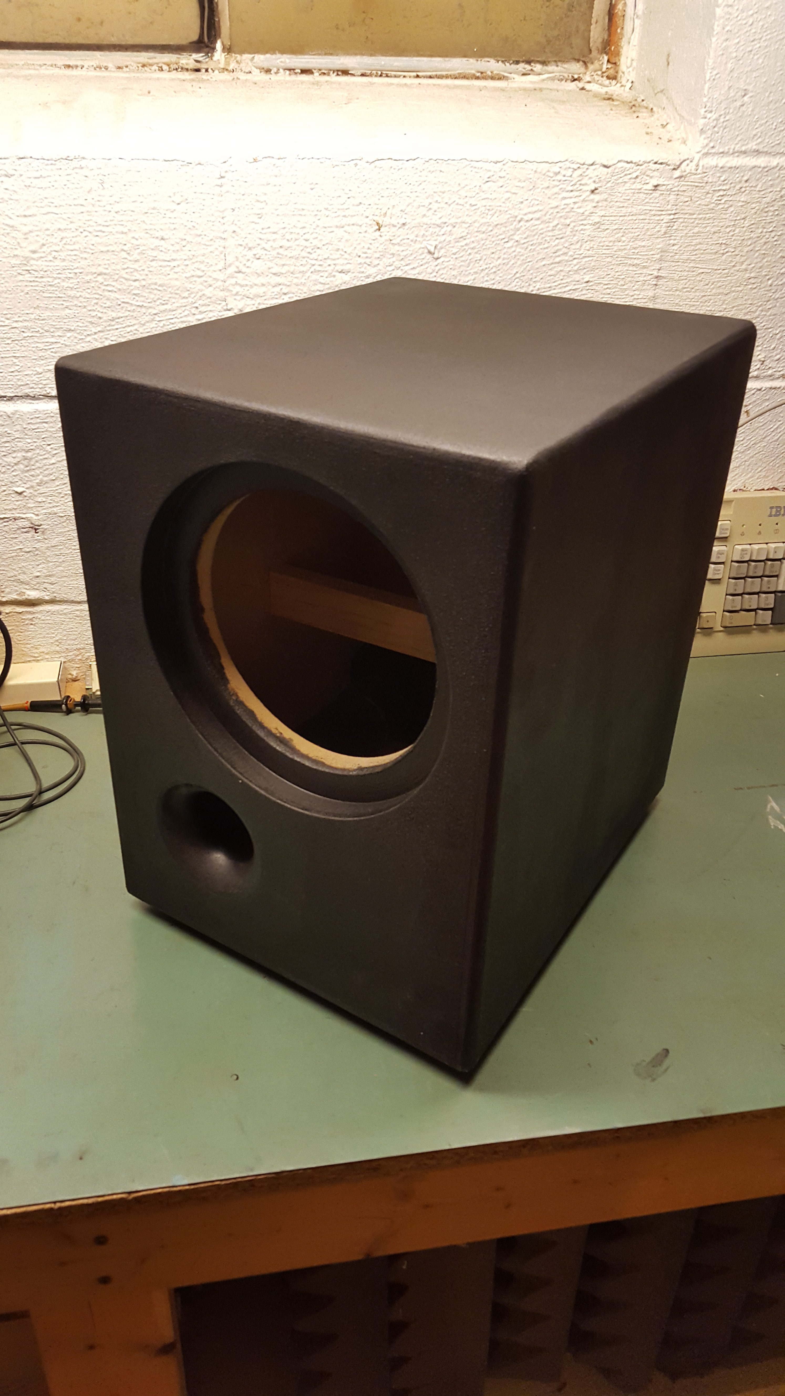
Indy 8 – Powered 2.1 system subwoofer
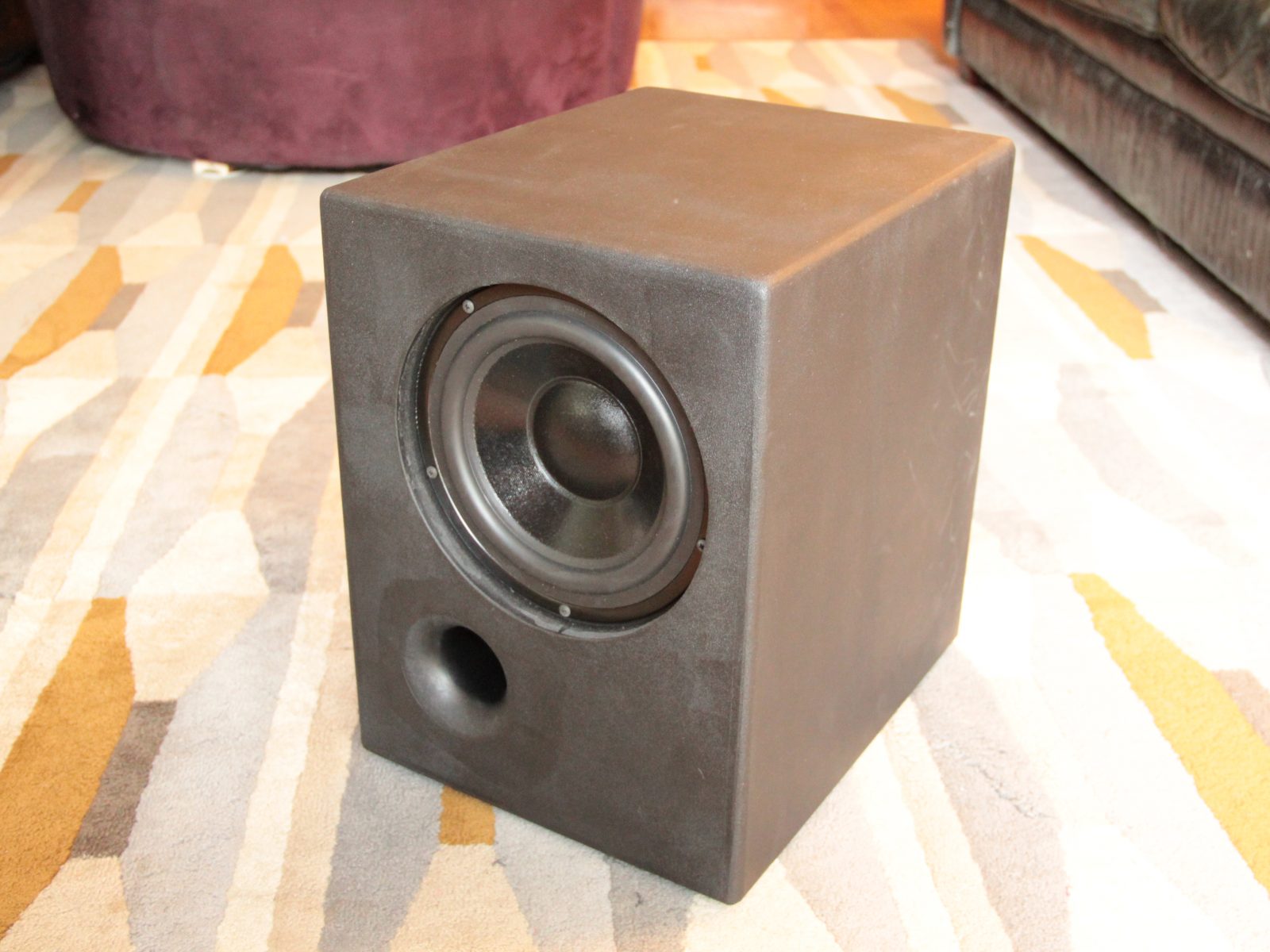
A self-powered 2.1 system contained in a compact 8” subwoofer enclosure. With the addition of a signal source and a pair of small satellites a fully independent full range system can be setup.

Design Goals
For the subwoofer, the design goal was strong output to below 40Hz suitable for a small room. The electronics were required to power the subwoofer and a pair of satellite speakers with an active filter on both sets of amplifiers for true bi-amplification. A simple analog crossover will be used with a fixed frequency of 100Hz, so the crossover slopes should be reasonably steep. All power supply, electronics, and controls will be fully integrated into the subwoofer cabinet.
Existing off the shelf 2.1 amplifier boards were not considered for this project due to what I consider a fatal flaw, the lack of a true high pass on the satellite outputs. Typically these board either provide a full range output to the satellites, or have a fixed slow slope roll off. This increases power to the small speakers, limiting output when the amplifier clips, and increasing distortion due to the small woofer working when it shouldn’t be. For that reason I wanted to design my own active crossover, and utilize full range chip amps to power the speakers.
Driver Selection
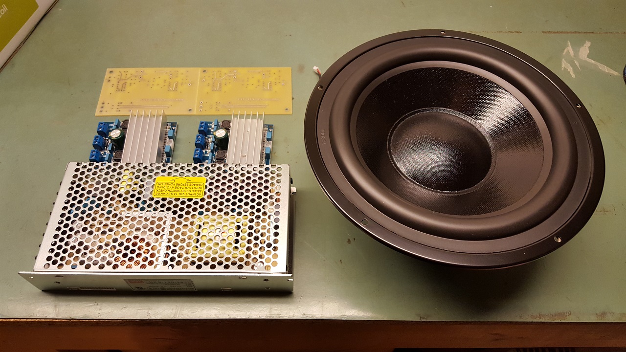
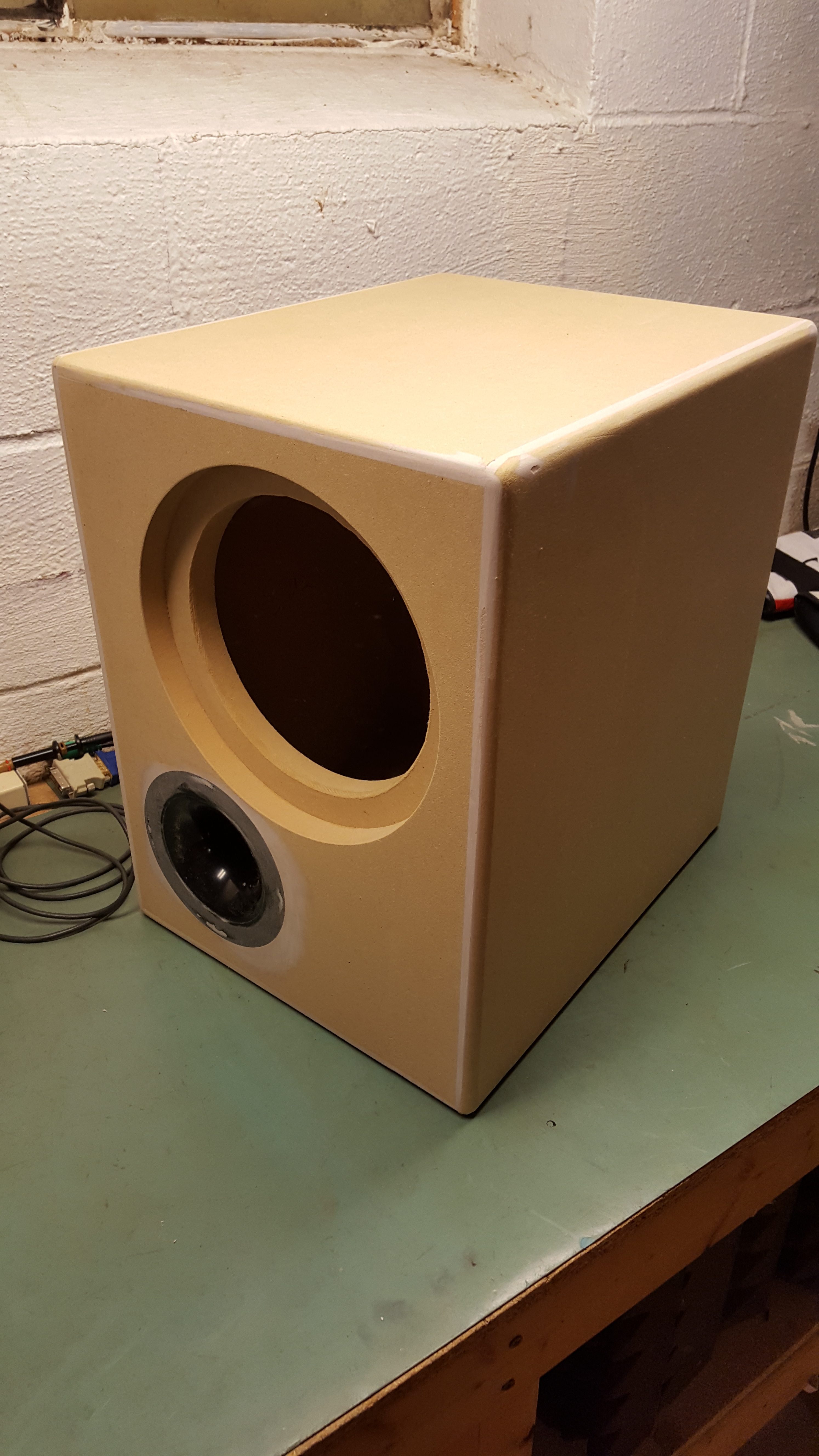
The Dayton SD215-88 woofer was chosen due to its proven use in reasonably small cabinets with good low frequency output, its low cost, and the dual voice coils allowing it to be powered from an inexpensive dual channel chip amp.
Enclosure Design
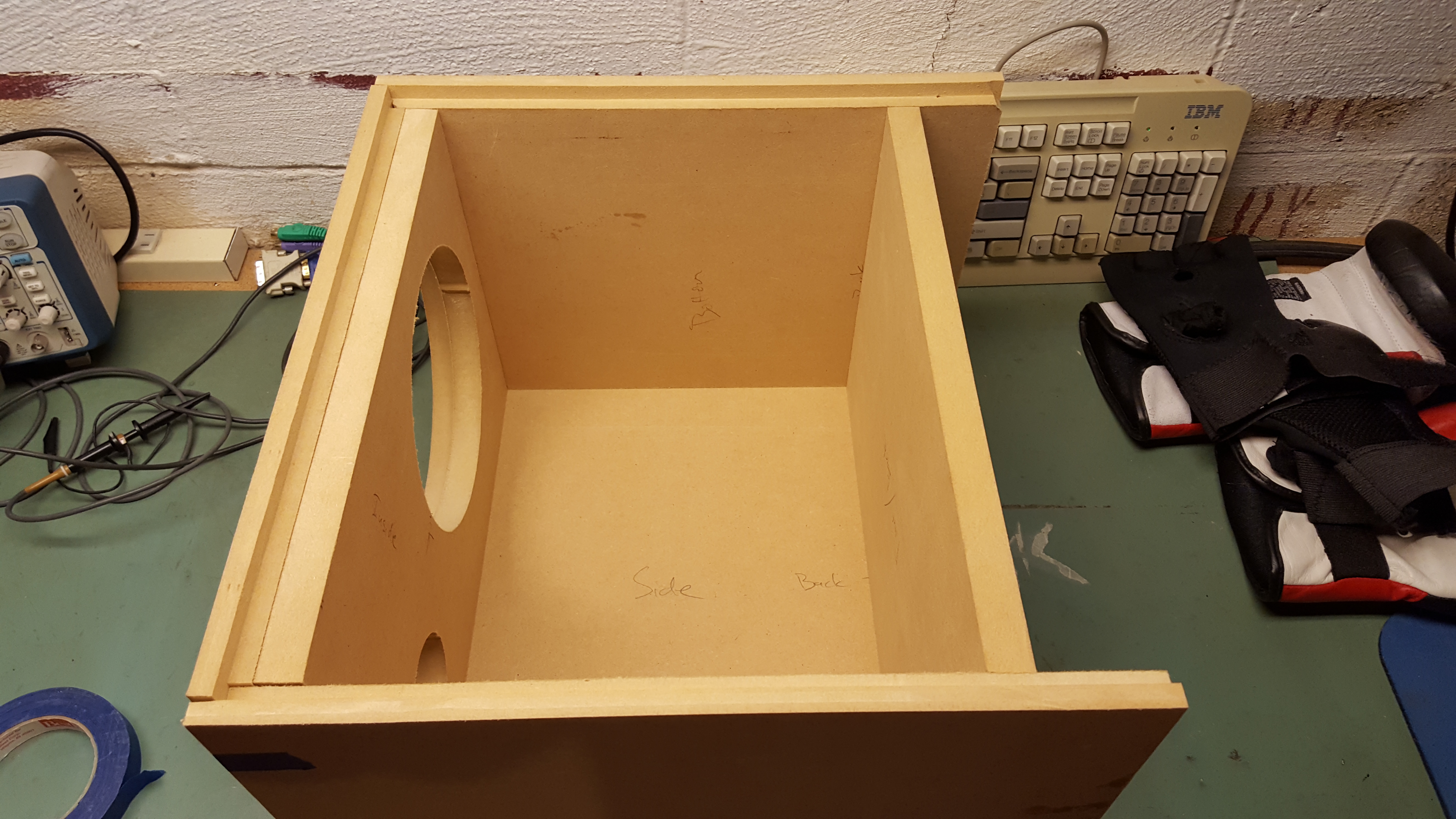
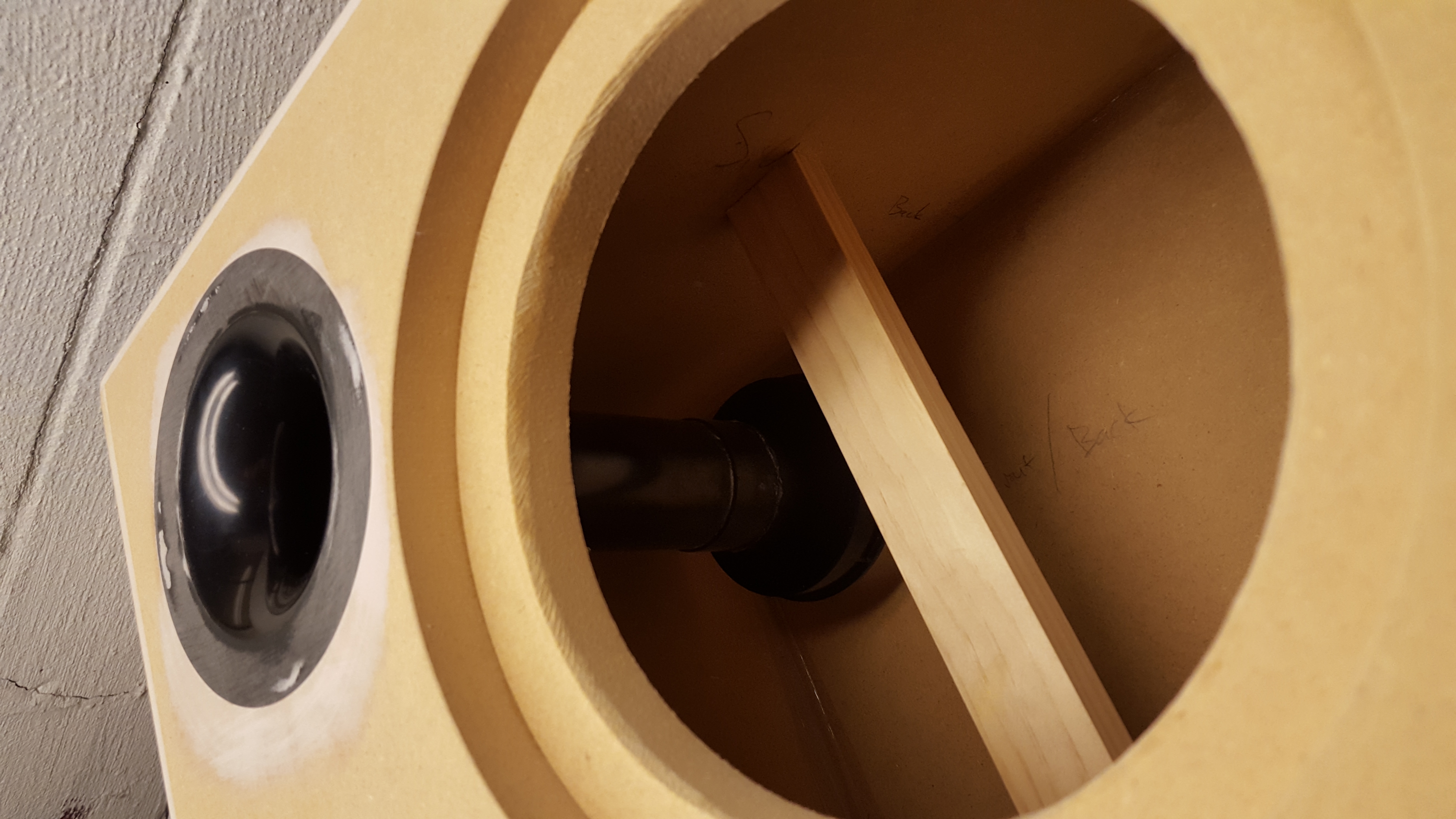
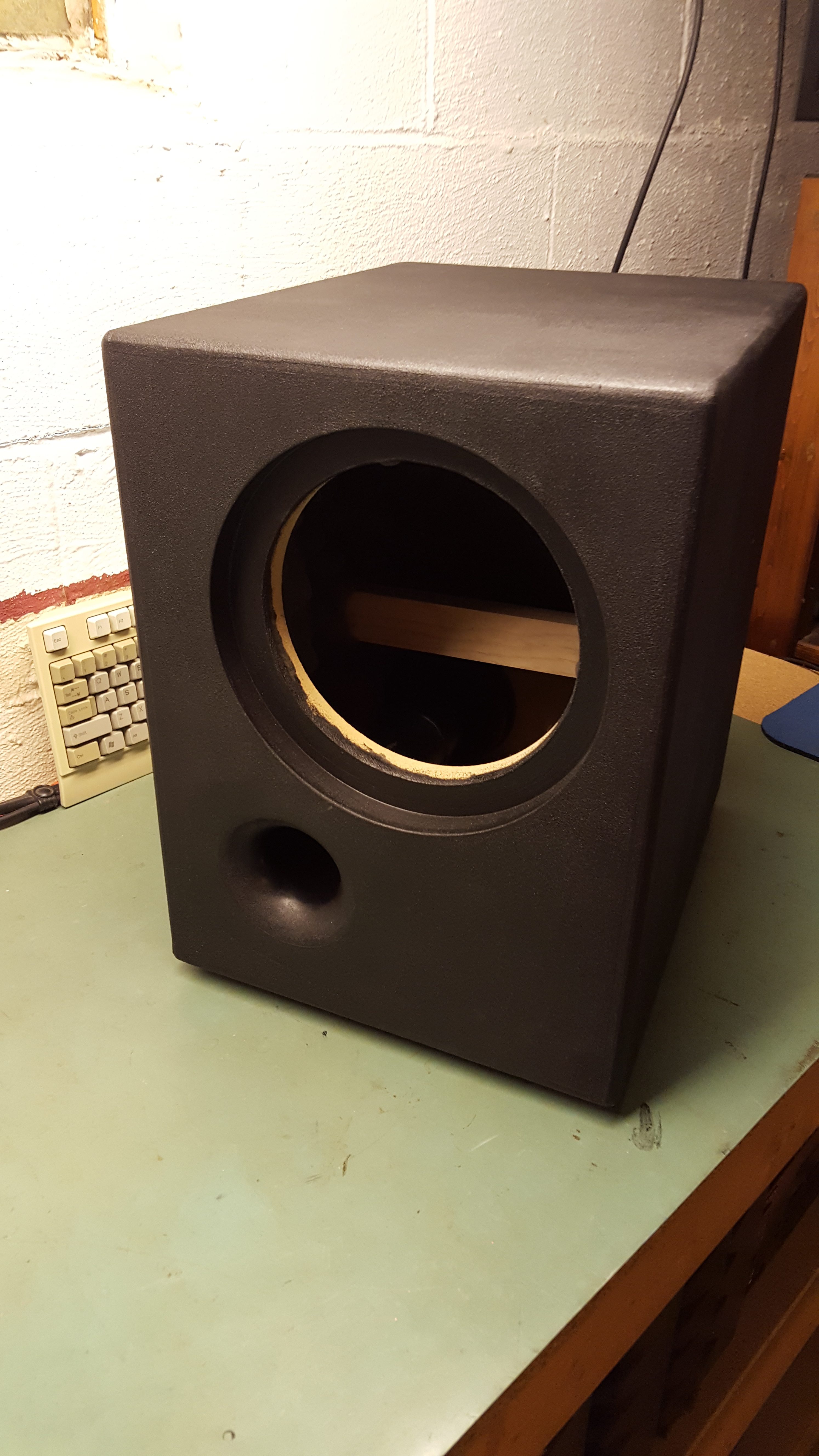
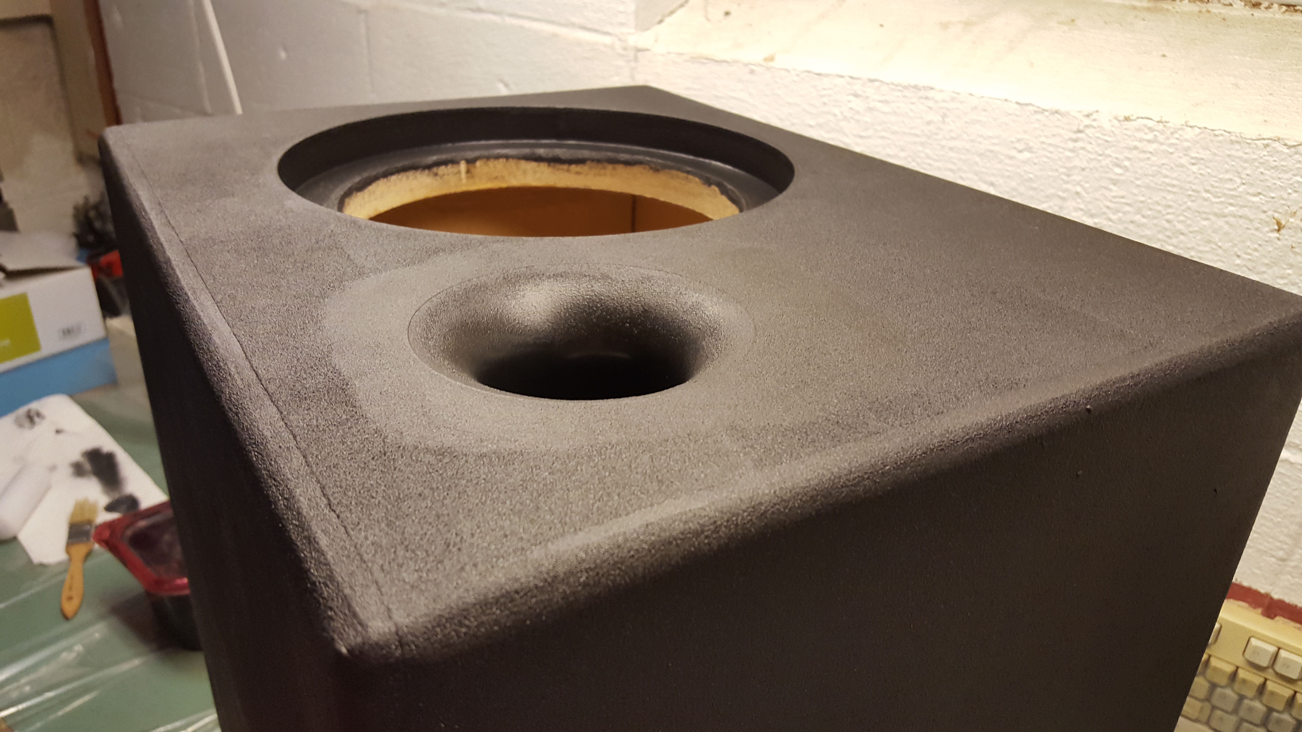
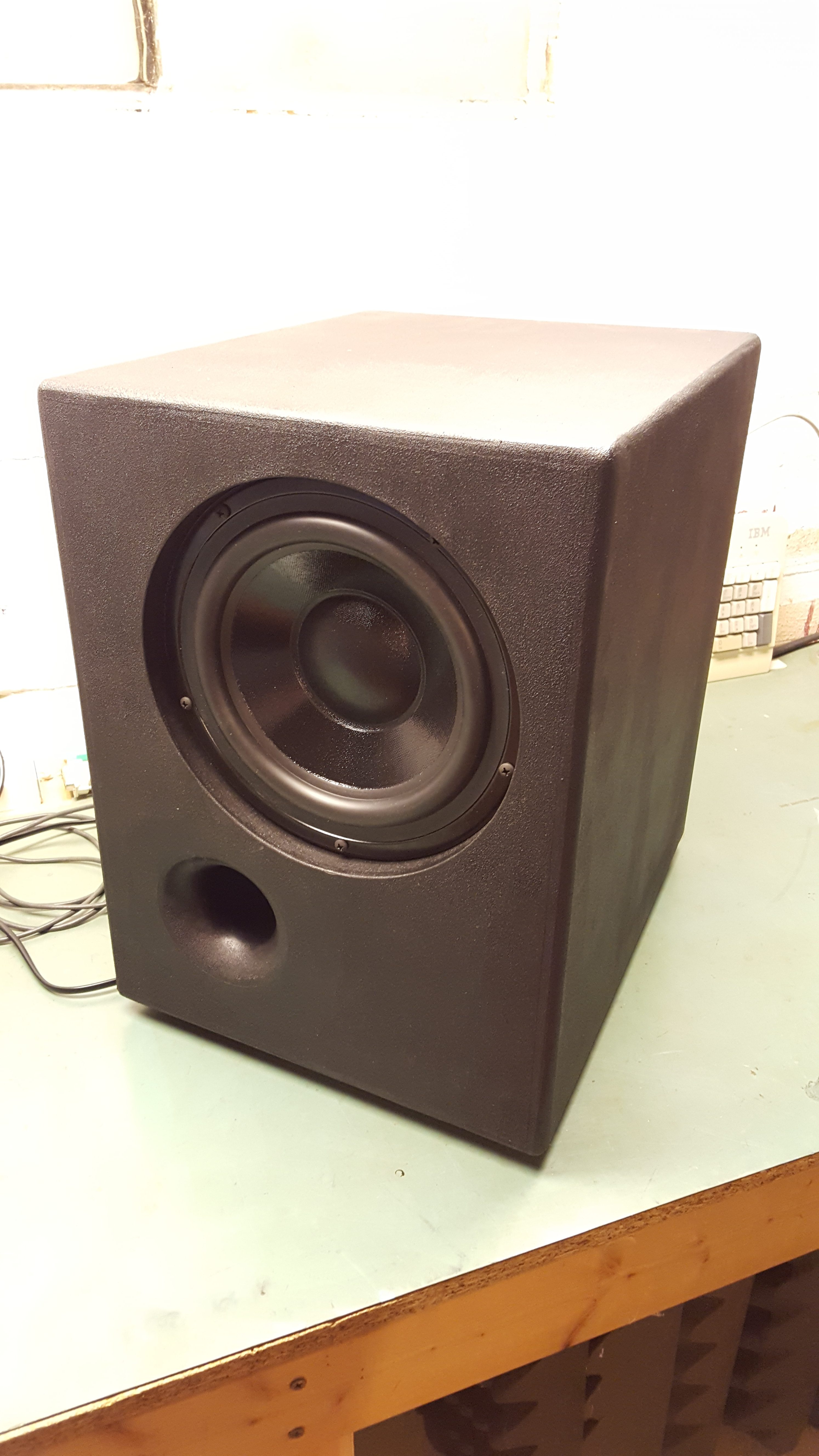
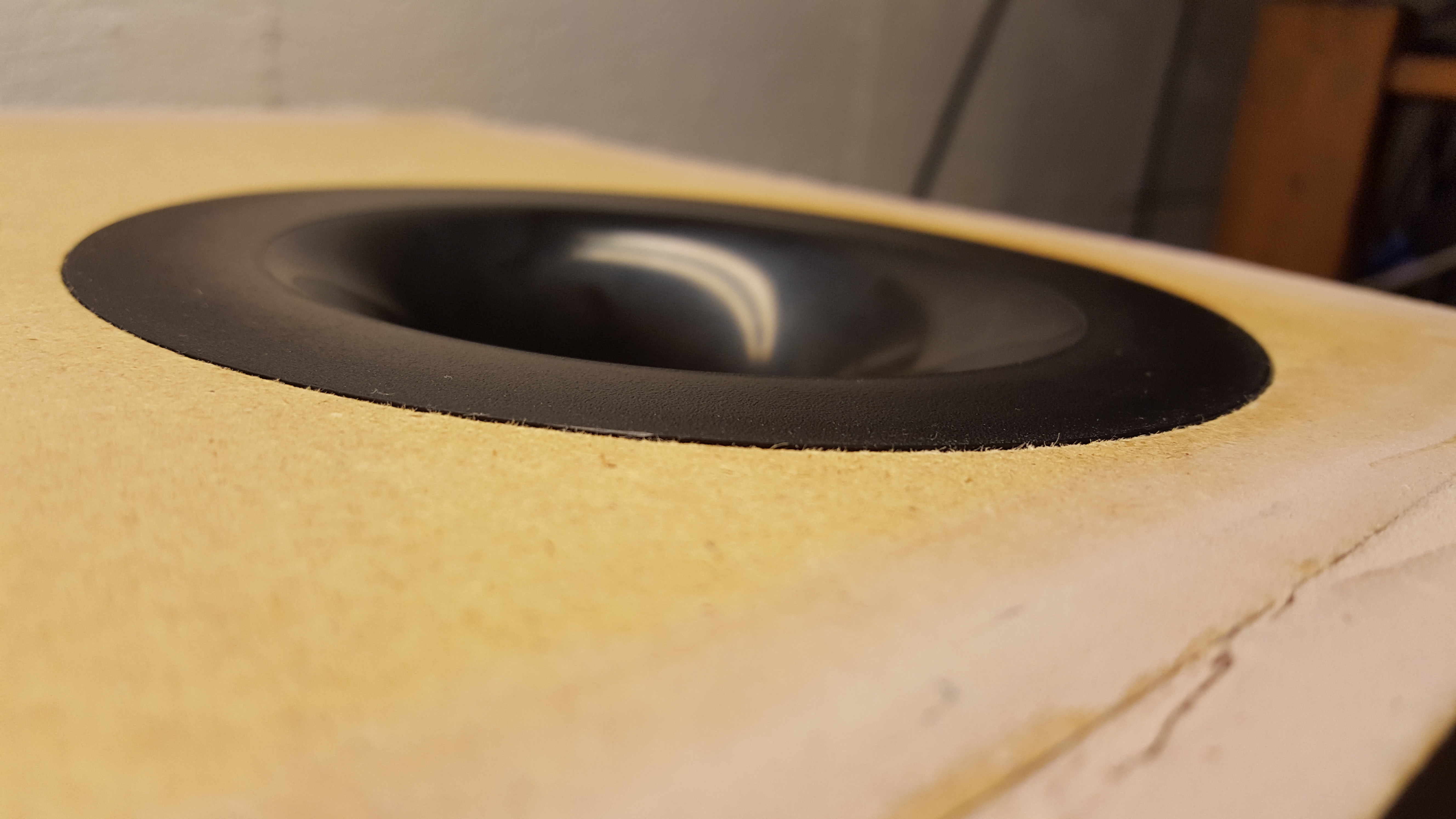
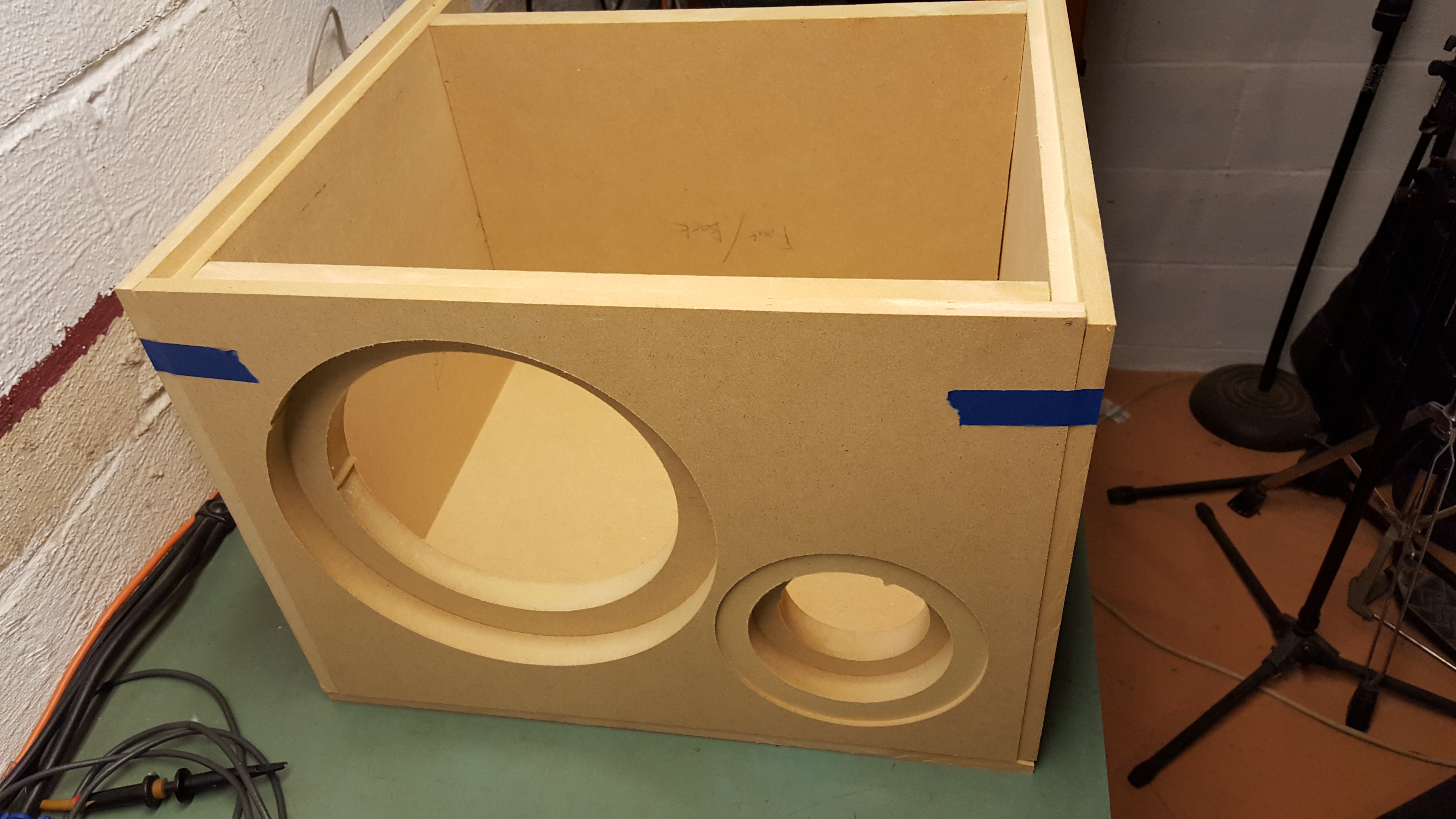
The enclosure is a simple trapezoid 12” wide, 15” deep, and 16” tall constructed from 3/4” MDF. The rear panel is inset 2” to accommodate the plate amplifier installation. The baffle is doubled with the 7.125” required internal cutout for the woofer concentric to an 8.75” cutout for recessing the driver a full 3/4” and allowing a simple circular steel grill to be placed to protect the woofer. A 2” Precision Port 9” long is used to tune the net 0.914 cubic foot box to 31Hz.
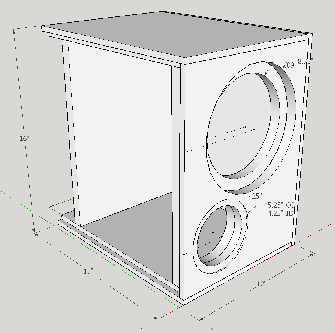
This gives the box a -3dB point of 36Hz with a physical limit on power handling of 40W due to Xmax at 43Hz. The amplifier is capable of 35WPC, and will be able to overpower the speaker but not enough to risk physical damage. Estimated peak output should be around 105dB at 70W.

Enclosure Assembly
The enclosure was built from raw MDF stock using only hand tools. The wood was cut with a skill saw and a clamped on aluminum cutting guide. Mating edges were cut with a 3/8” rabbet bit using a hand held plunge router. All cut outs were made with a Jasper Circle Jig and router. The lack of a table saw led to some tolerance issues on the box edges, so a thicker adhesive was used to help fill gaps while assembled.
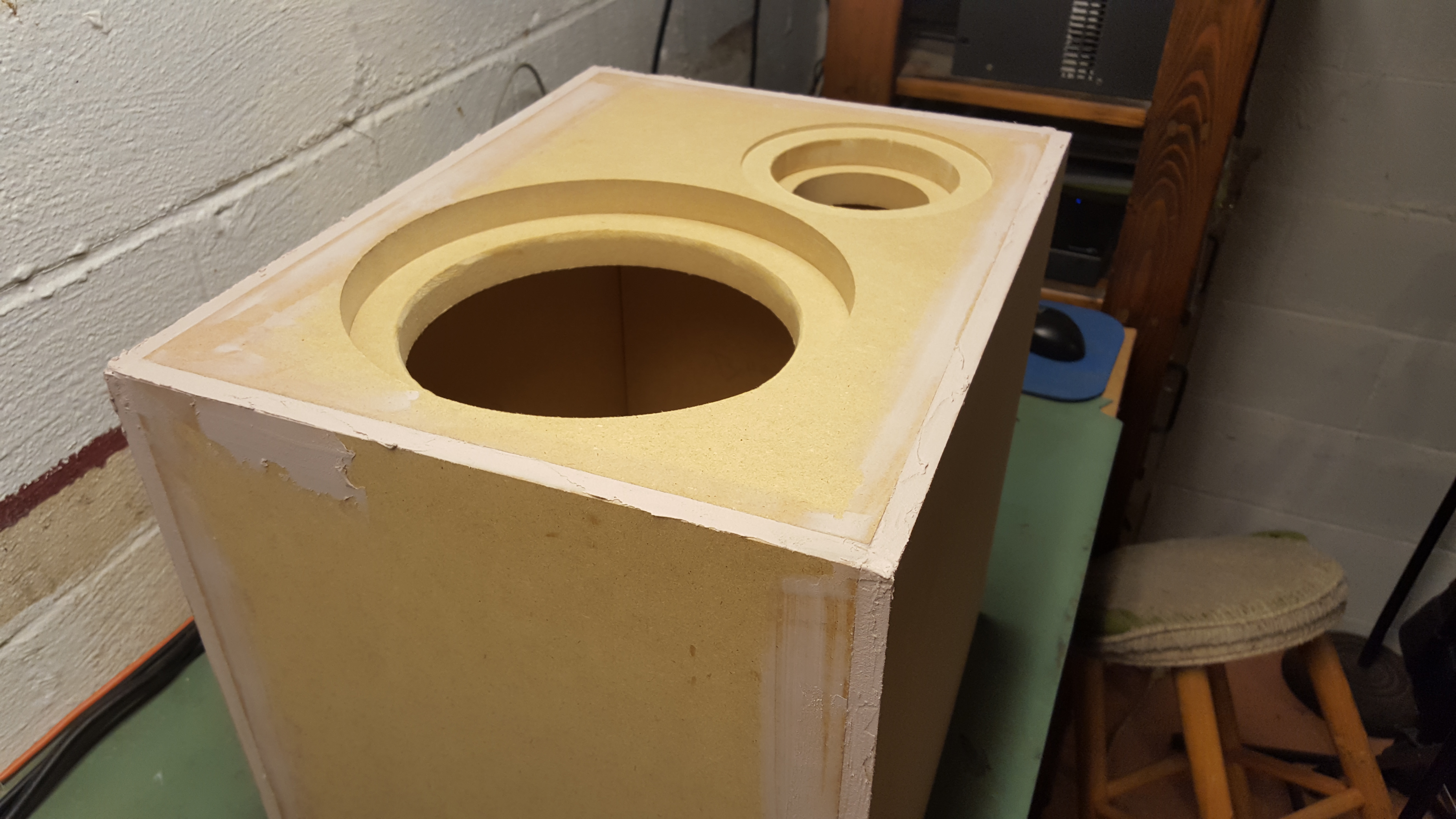
Bondo was used to fill the gaps, which were then sanded down with a hand held belt sander, then rounded off with a ½” roundover bit in the router. A few goof ups due to hand holding the router against the bit’s bearing were cleaned up with the belt sander.
The Precision Port was recessed using a 3/4” straight bit in the Jasper Circle Jig, and flush mounted with the front. Some Bondo was used to hide the seam and the port was sanded flat with the face of the cabinet so the finish would be seamless.
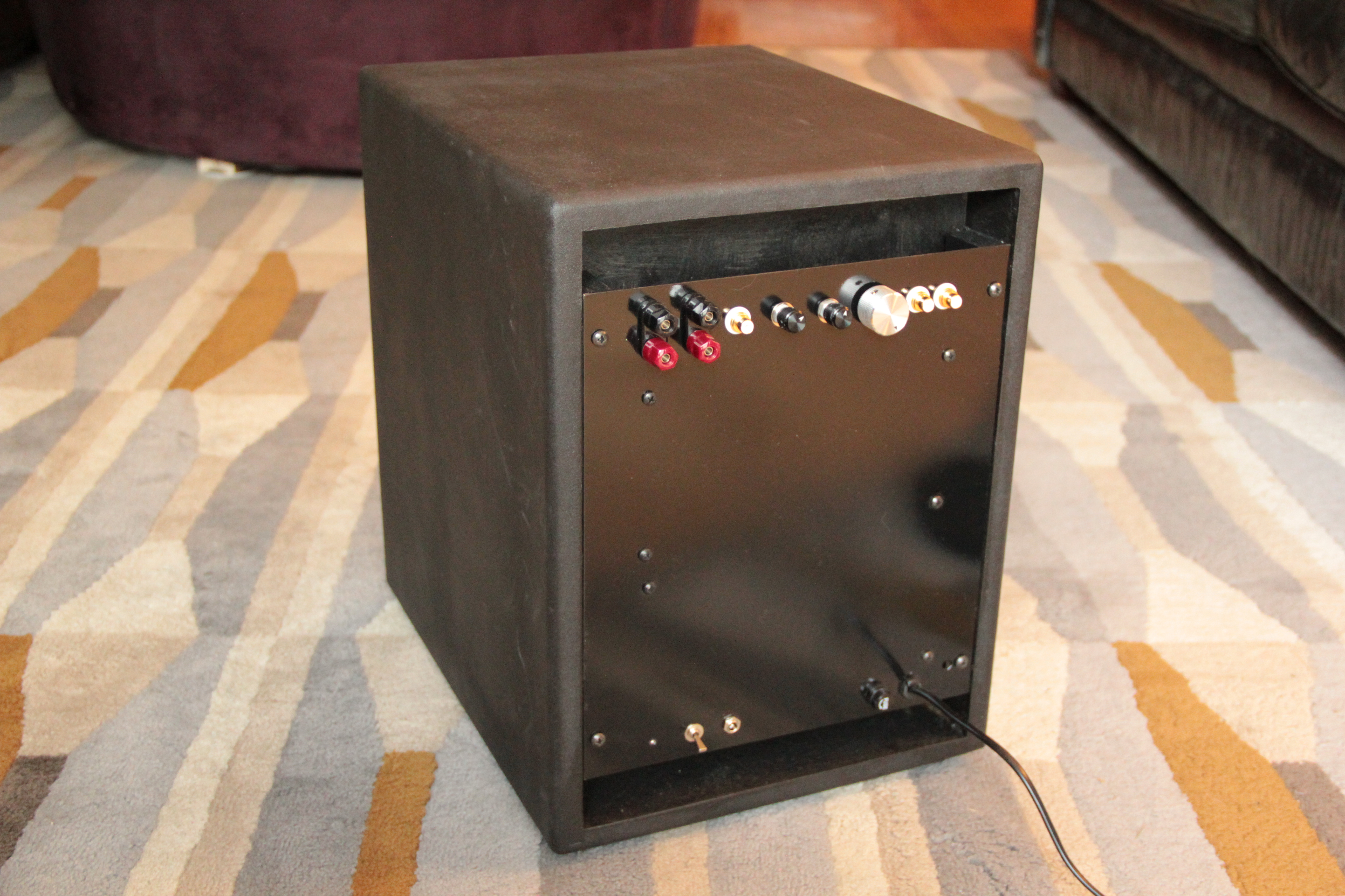
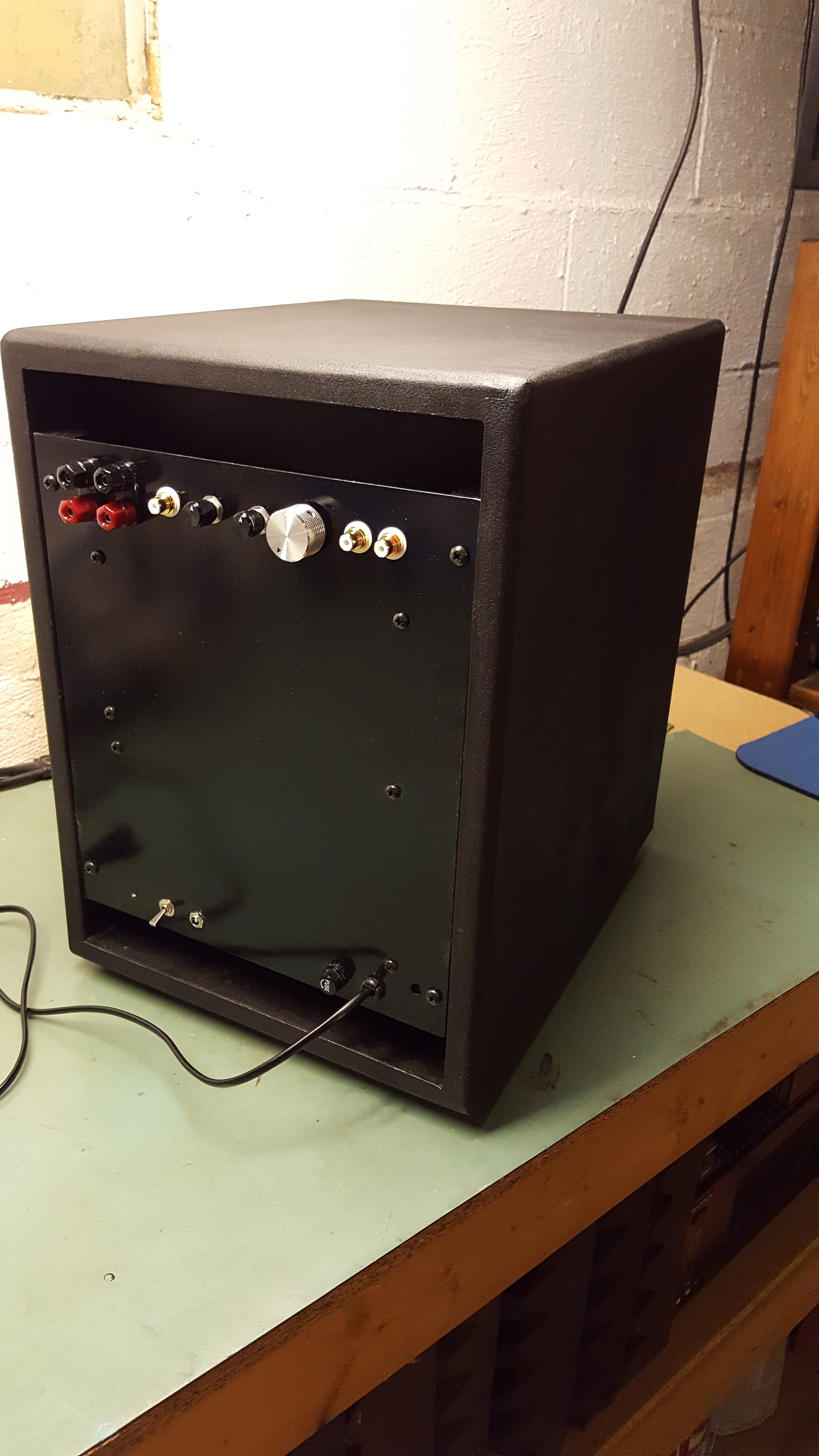
A single side to side brace was added using pine 1×2 stock, which was also used to provide rails in the rear recess cavity for mounting the plate amplifier.

The inside of the enclosure was covered in egg crate foam for some damping before finishing and assembling. The enclosure was finished with black Duratex and a white small cell foam roller with the intention of being a lighter texture than the typical finish using the included blue roller. My supply of Duratex was low, so I didn’t have the time or supplies to sand and re-coat. The finish ended up with some texture ghosting where the Bondo was applied that I was unable to smooth out. I intend to get some more Duratex at some point, then sand and re-apply the finish to this cabinet.
Crossover Design
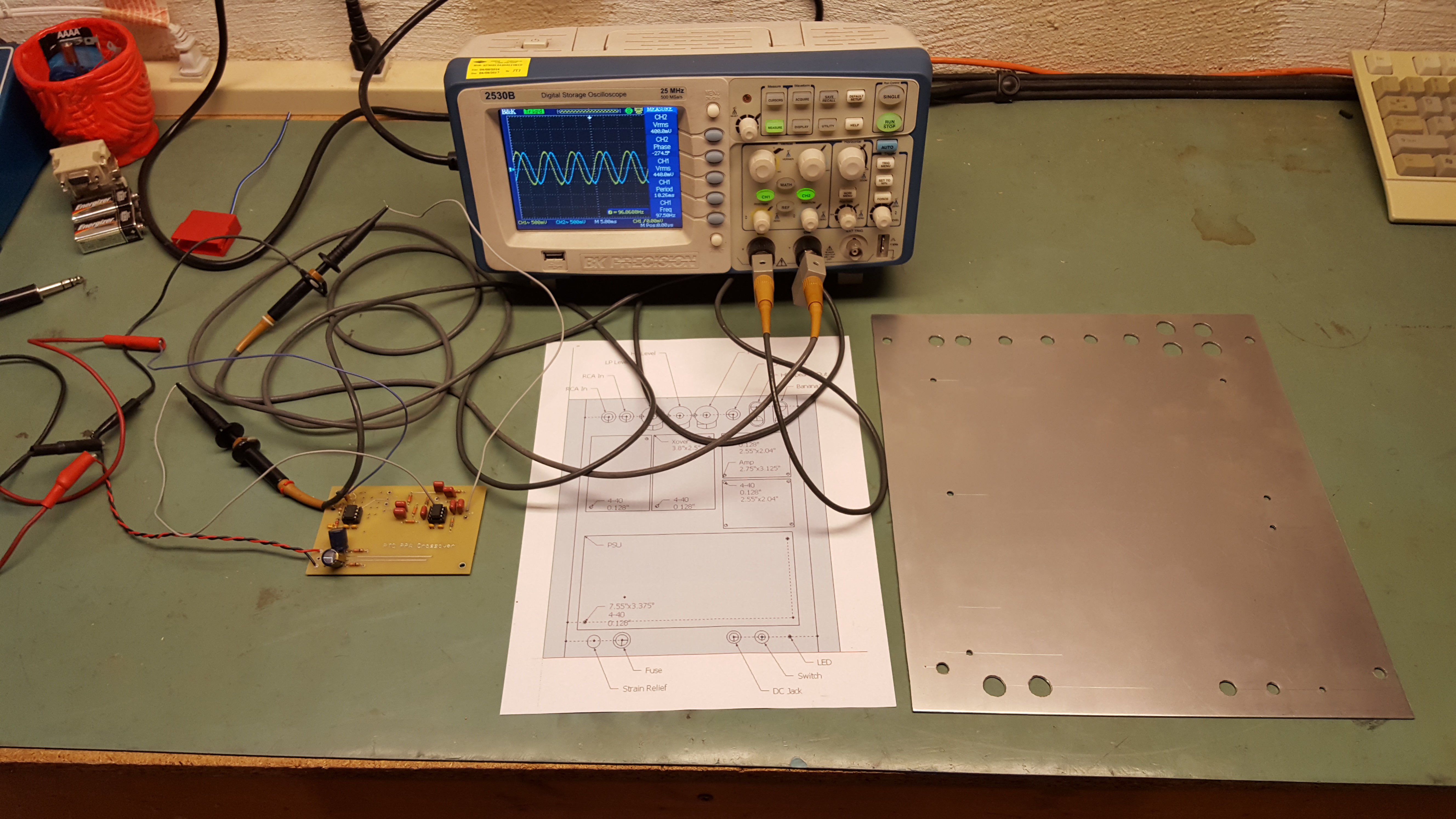
The crossover in this project is a custom designed active filter at 100Hz to provide signal to the pair of Parts Express TDA7492 amplifier boards. The design is textbook 3rd order Sallen-Key butterworth filters with a gain block to overcome an audio taper volume pot.
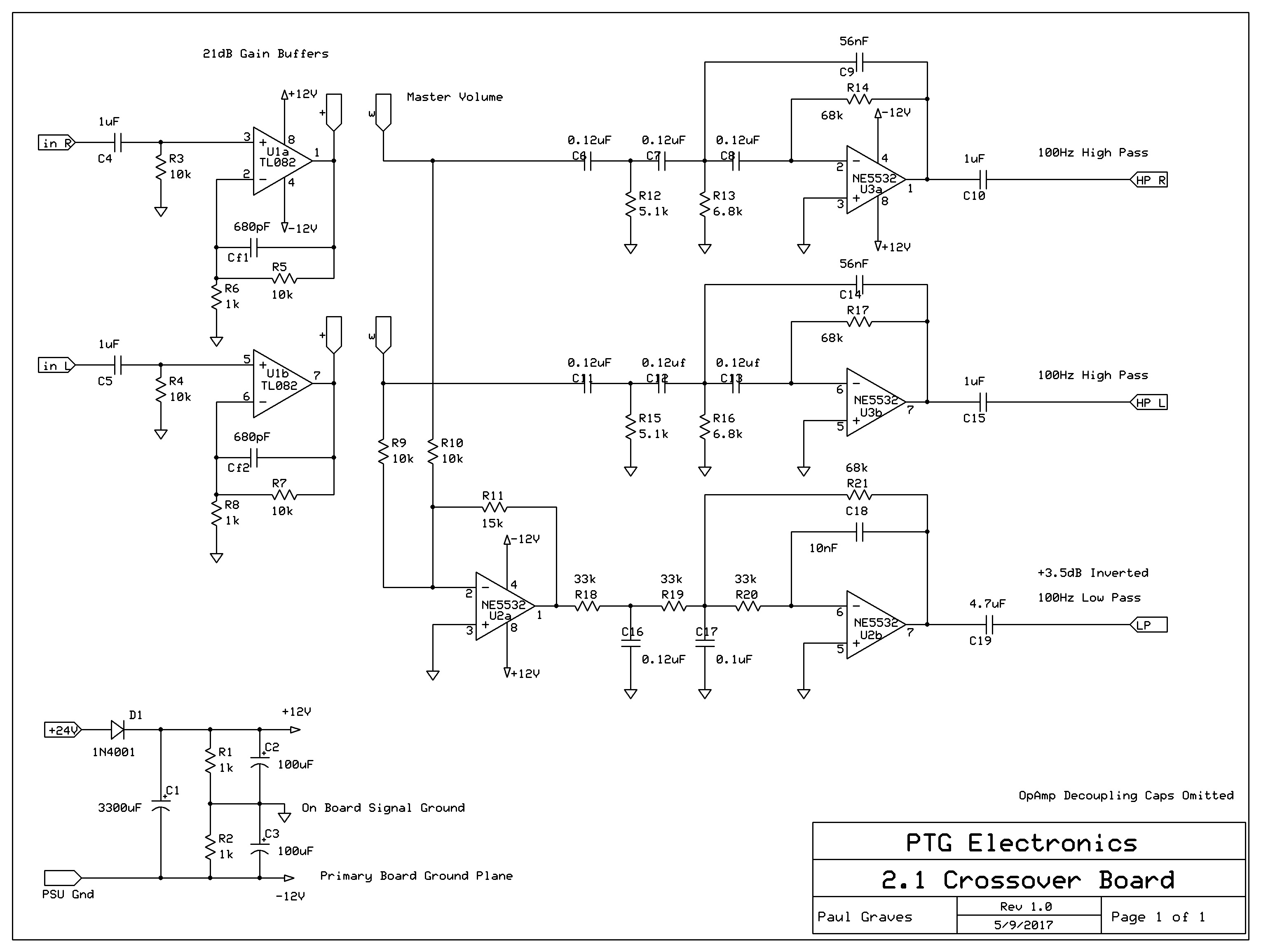
This schematic is a dedicated design for this purpose. The master volume may be connected before the gain buffers, or after. If the master volume is connected after the buffers as shown in the schematic, there will be a risk of clipping the gain block given sufficient input signal. With 21dB of gain and a 24V supply, the op-amp will clip with just over 1V peak input, which may be a concern. The advantage of putting the volume after the gain block is an improved noise floor, however the potential to clip may be a larger problem. When built using a volume control in front of the filter board, simply install jumpers where the master volume connections would be. A complete design package is available for those that would like to prototype this design themselves.
In the ZIP file is a BOM for purchasing parts, and the files required to purchase the boards. To open the schematic and board layout files you’ll need software from ExpressPCB. the software is free, easy to use, and has direct functions to submit your order. Total cost for building these yourself is just under $60. That is a premium over pre-built 2.1 boards, but still cheaper than DSP options and worth the cost to provide that true bi-amplification in my opinion. The Mini DSP 2X4 would be an upgrade option at $80 for this project, but would require an additional power regulator to provide the 5V for the board. Using the DSP board would allow far greater flexibility and tuning options.
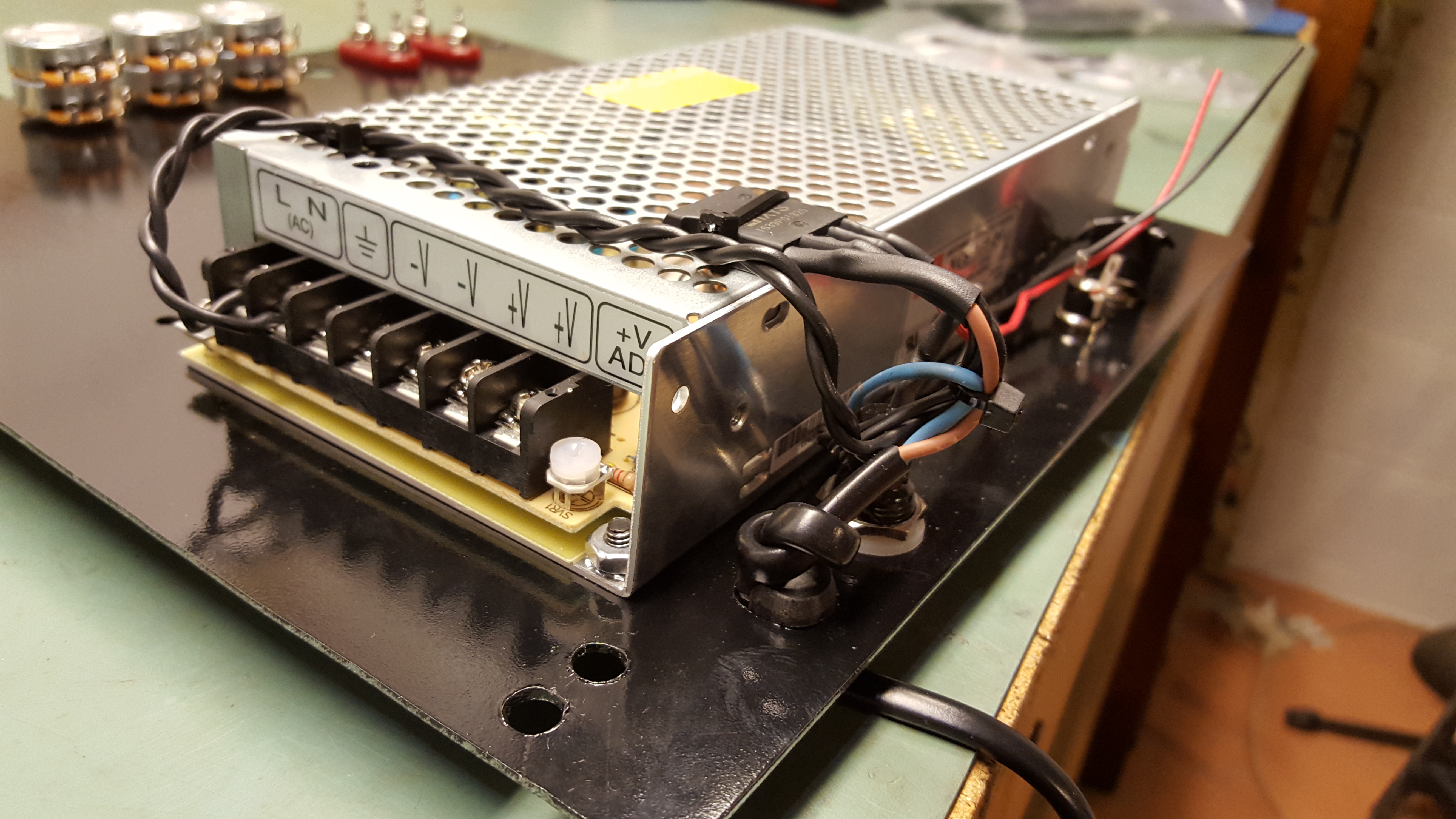
For this build I had a pair of prototyped PCB assemblies on hand from the PPA 100 project completed the year prior that contained the layout for the filters needed. This cut the crossover board cost to under $20. The boards were modified to be powered from the single ended 24V Meanwell supply, and populated with values to provide the 100Hz crossover at 18dB / octave.
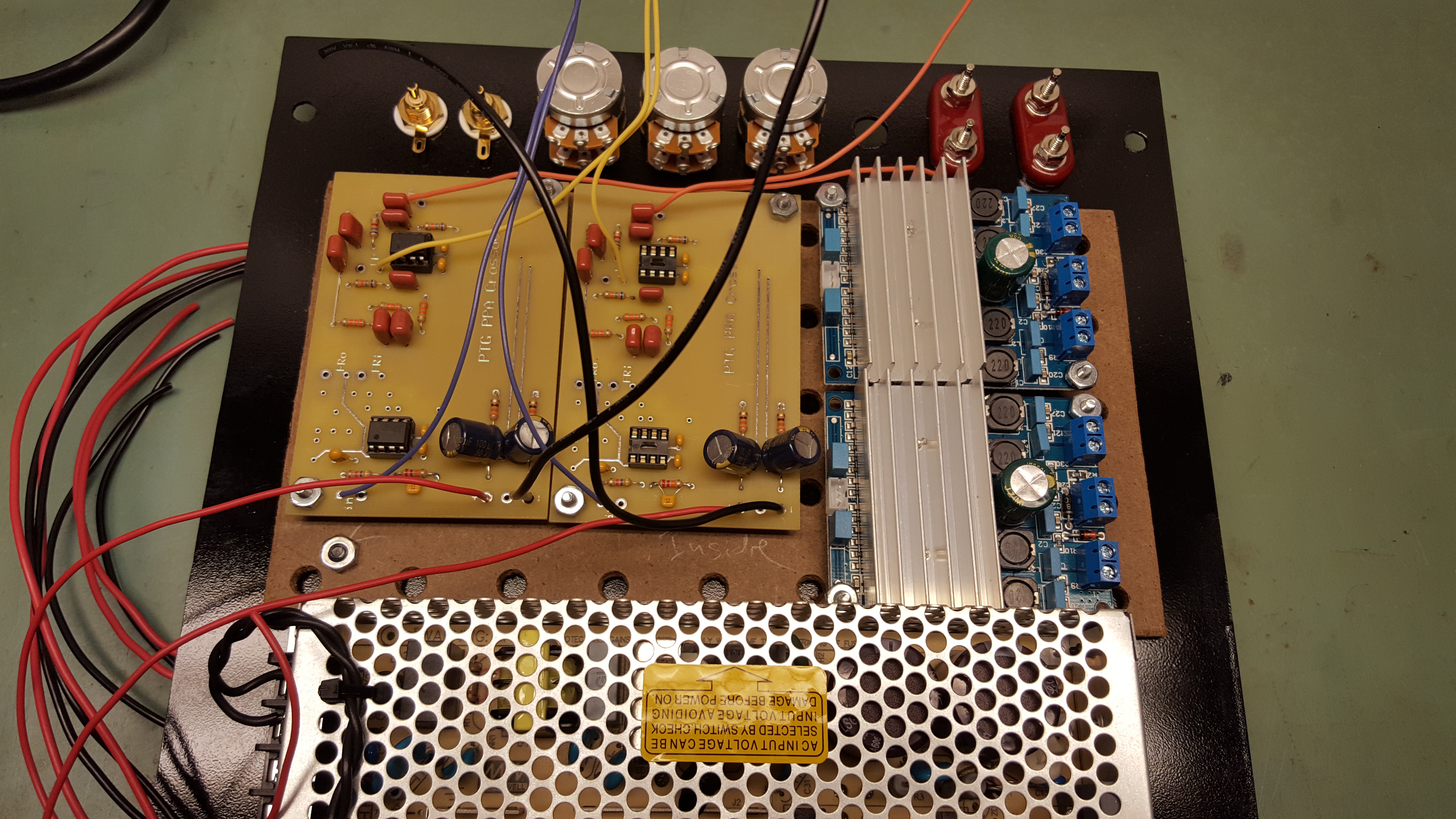
All parts were laid out in SketchUp to create the mounting plate for the electronics with all required connectors.
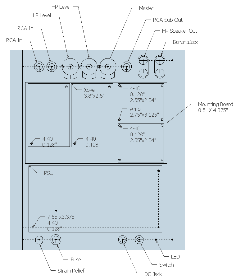
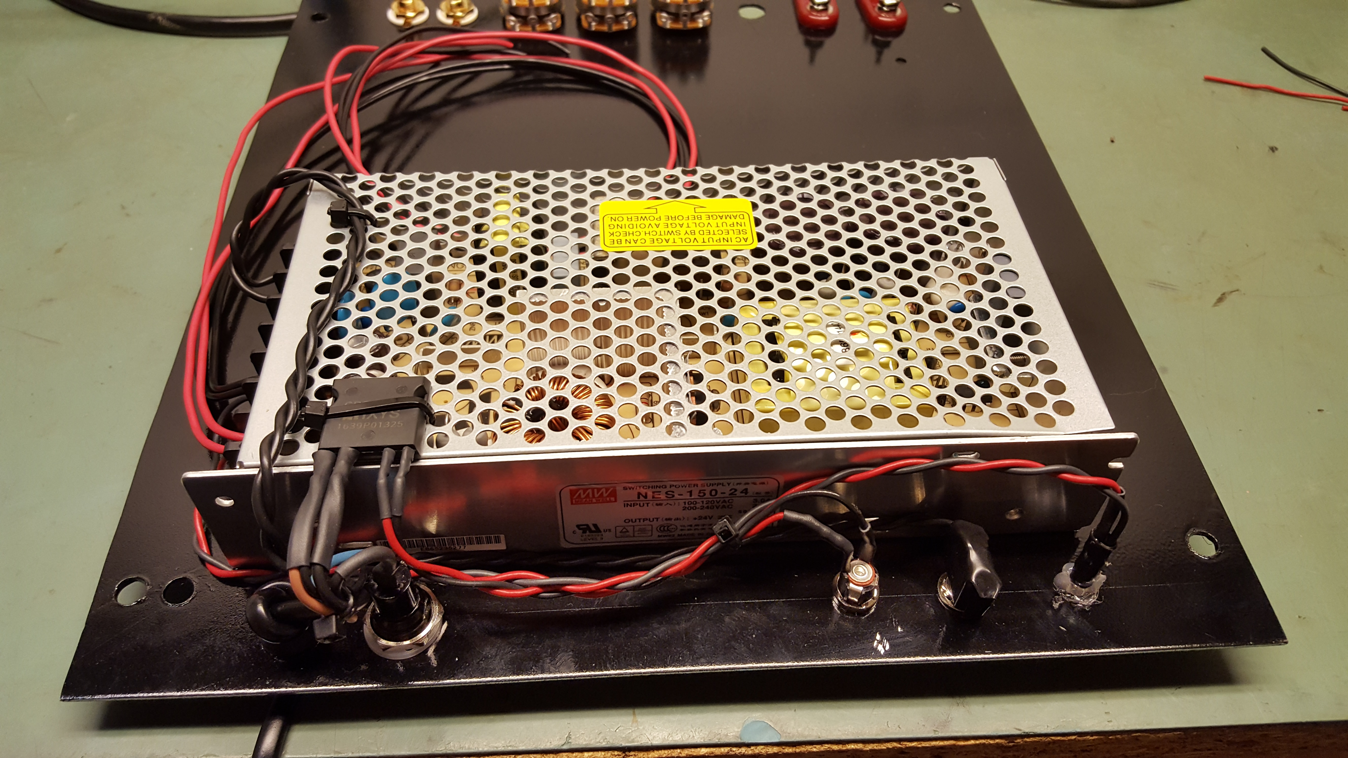
The electronics were all assembled onto a steel plate painted black to be mounted on the back of the woofer enclosure. A bit over an inch of space was allowed at the top and bottom of the plate to allow a channel of air flow to remove heat.
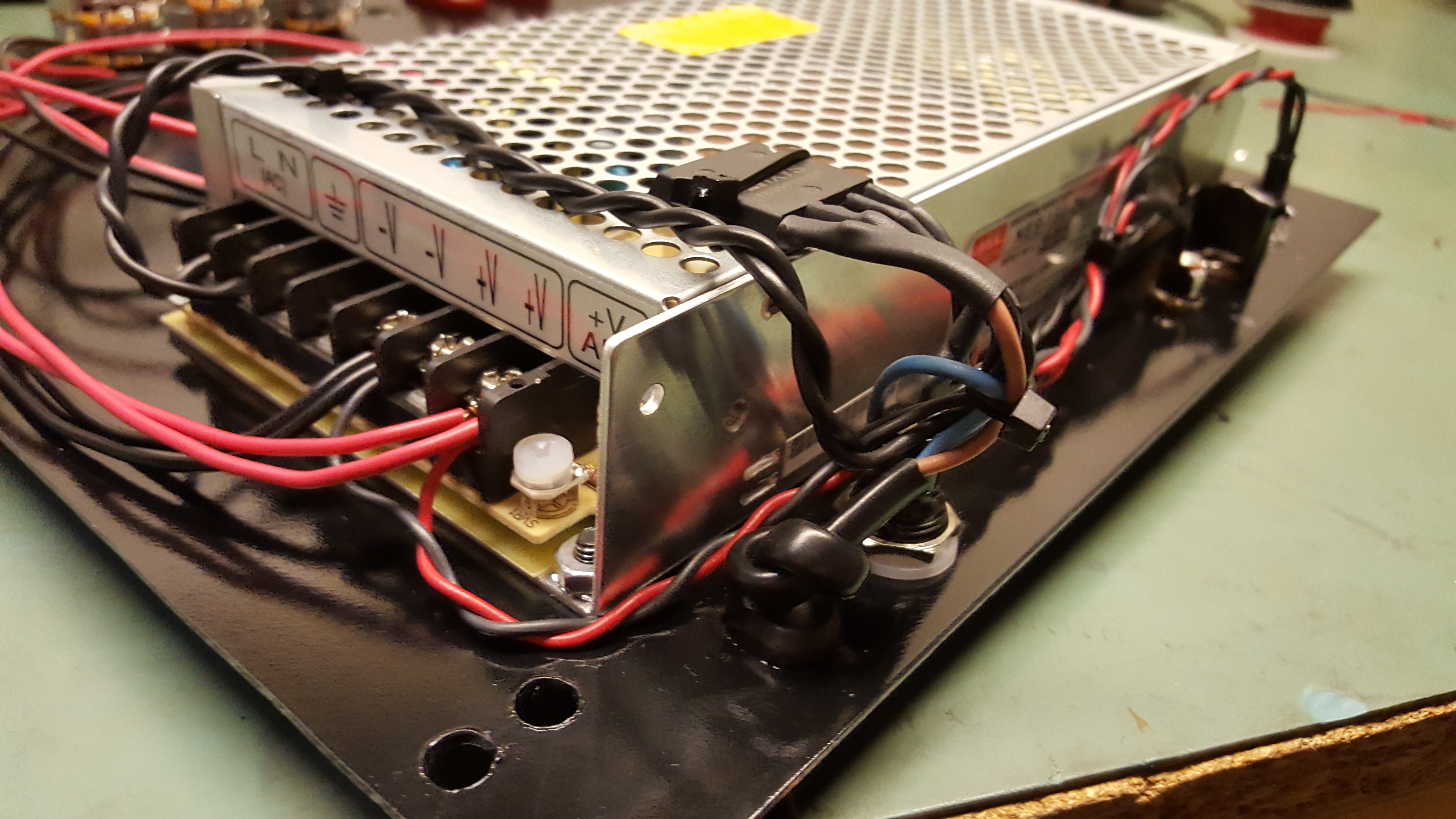
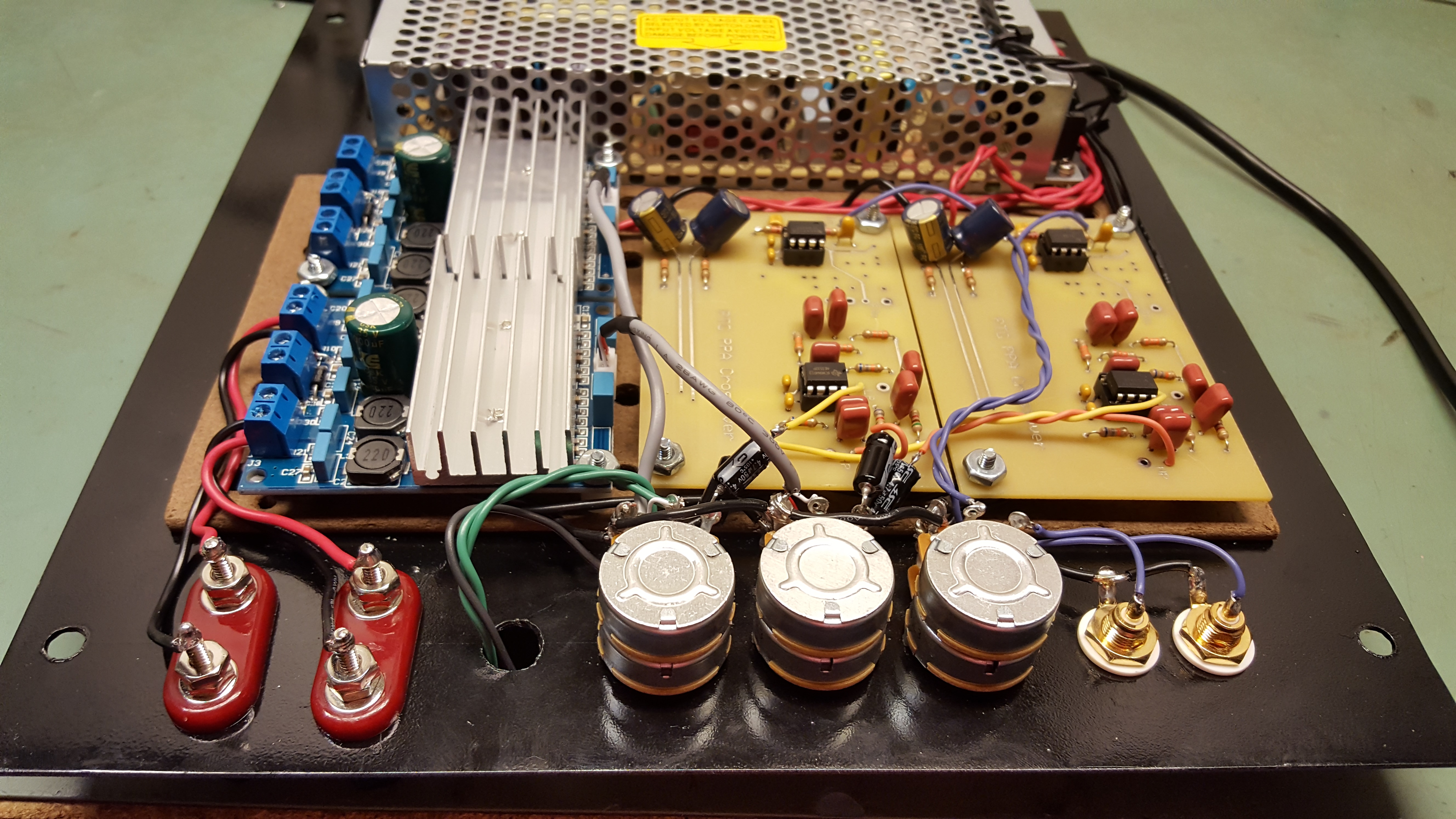
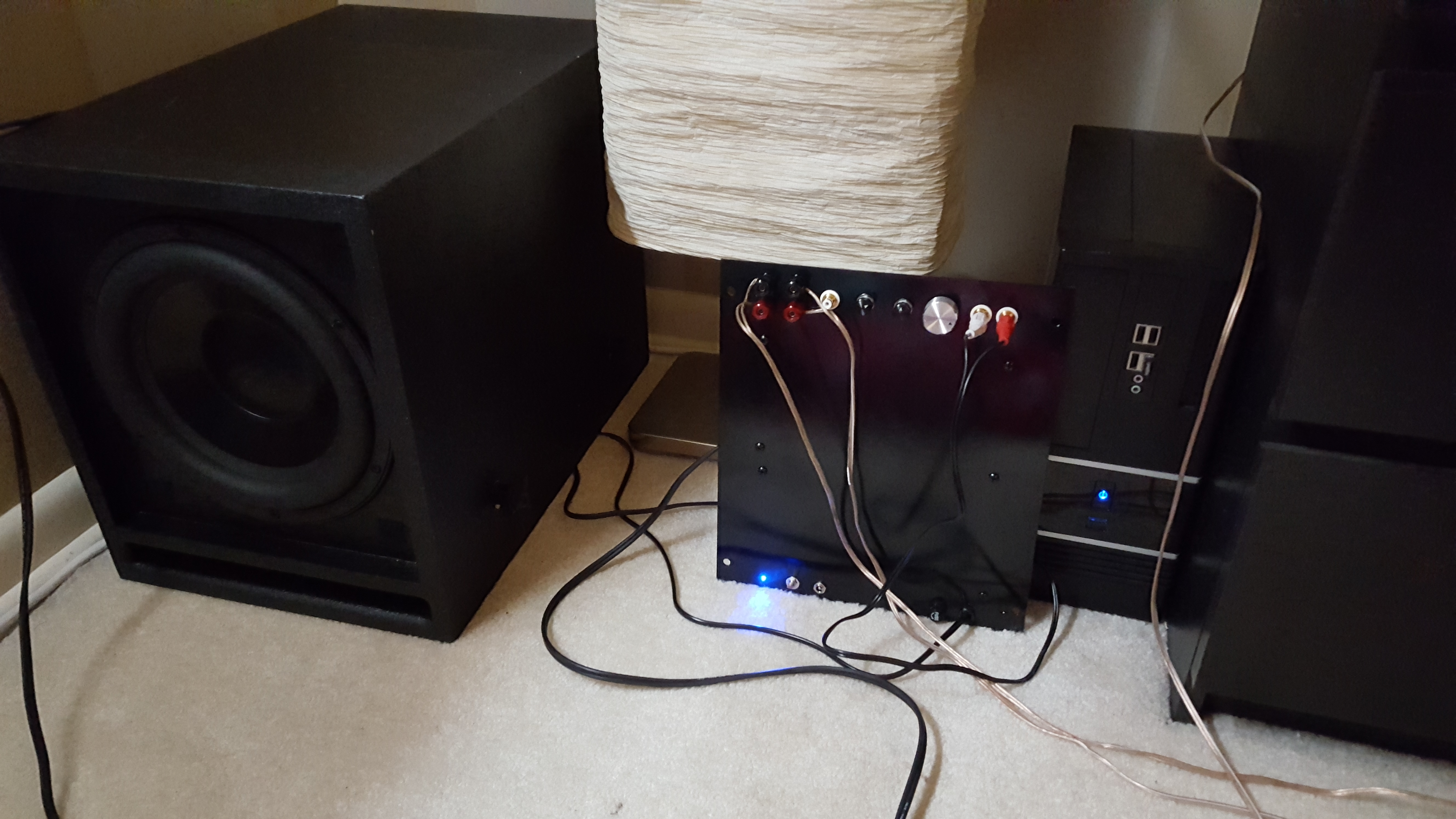
Additional electronics were added to the plate including the power circuitry, a remote turn on solid state relay, a blue power indicator LED for optimum sound, and independent level controls for master level, the high pass amplifier, and the low pass amplifier.
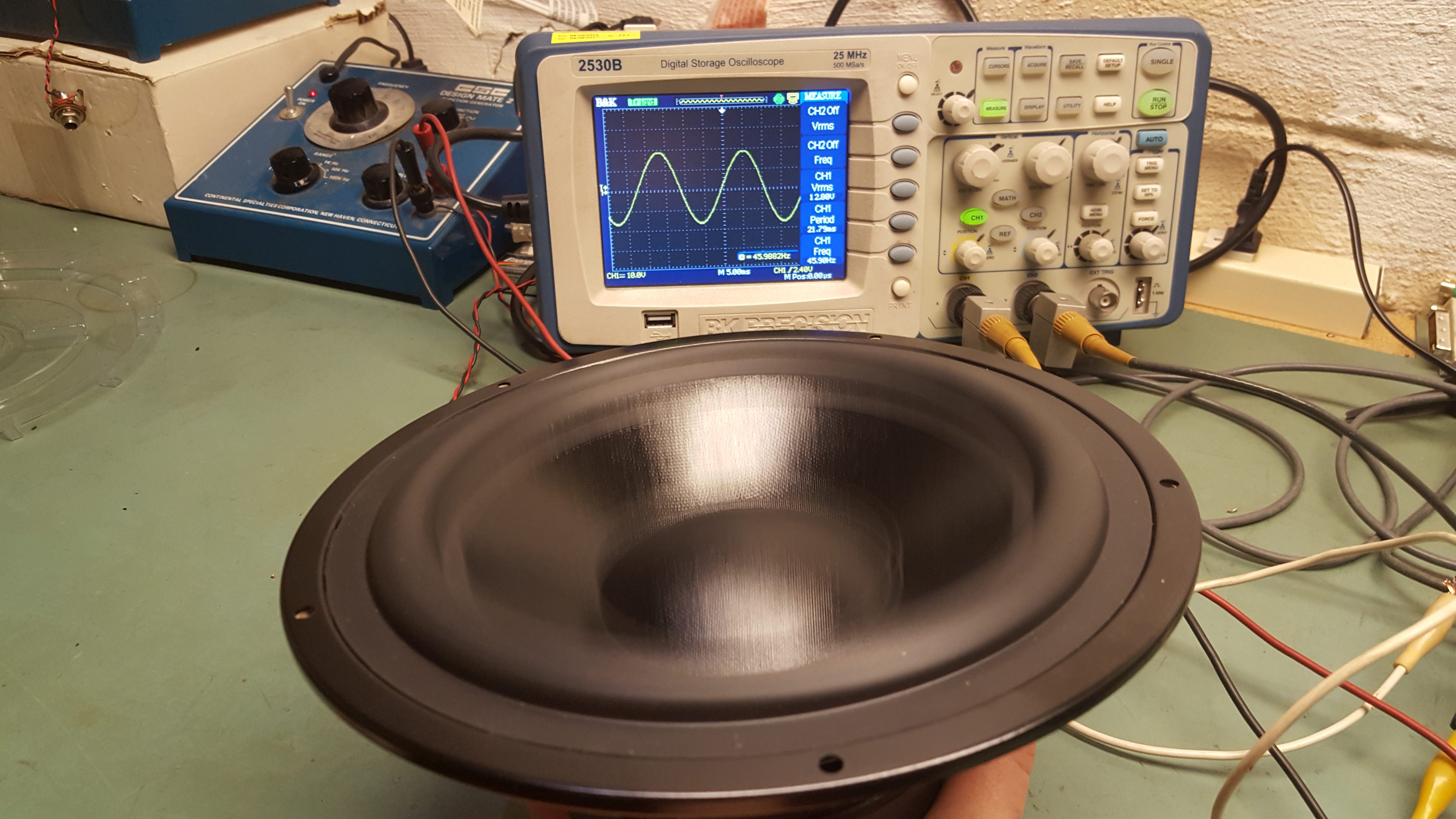
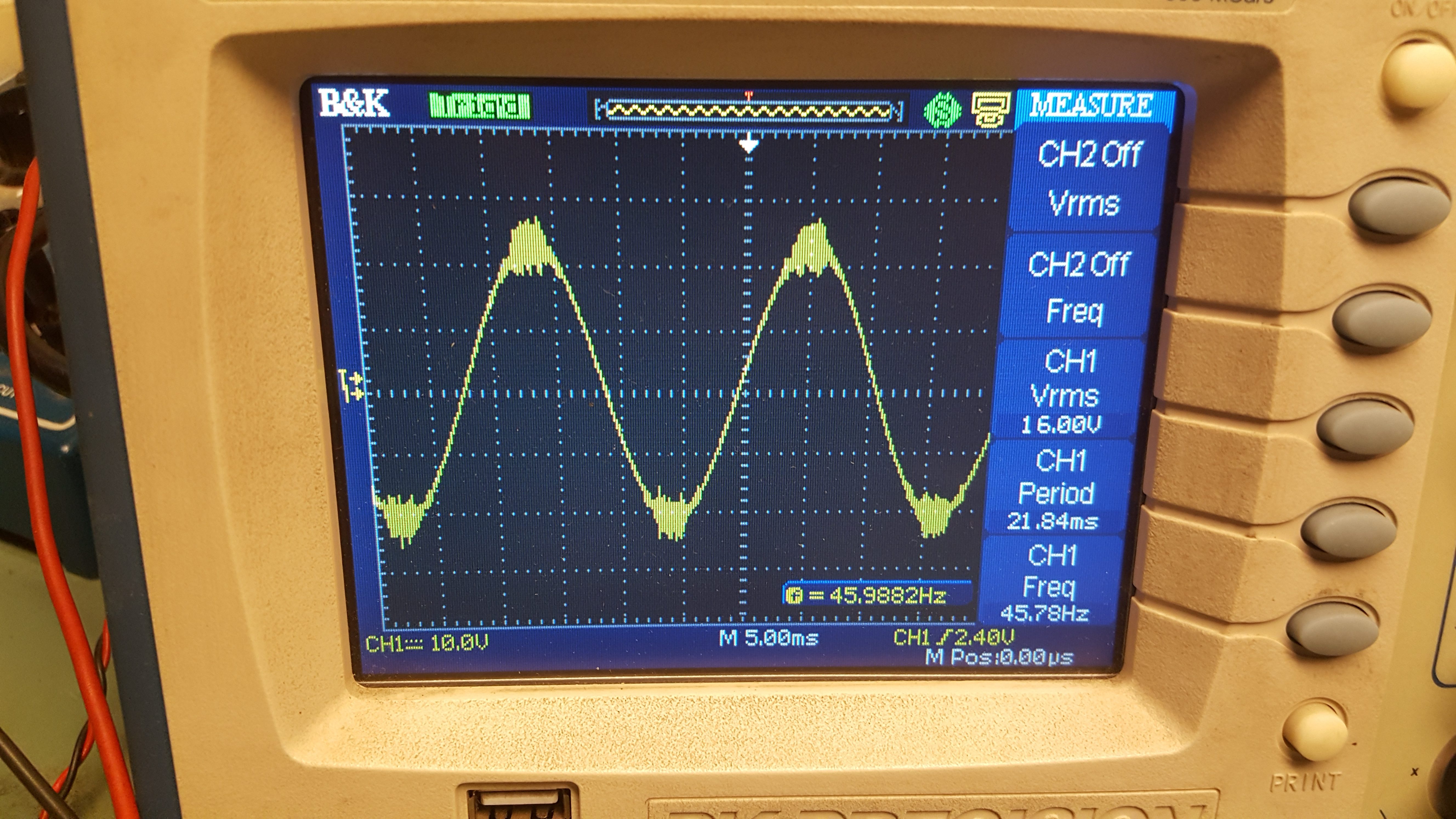
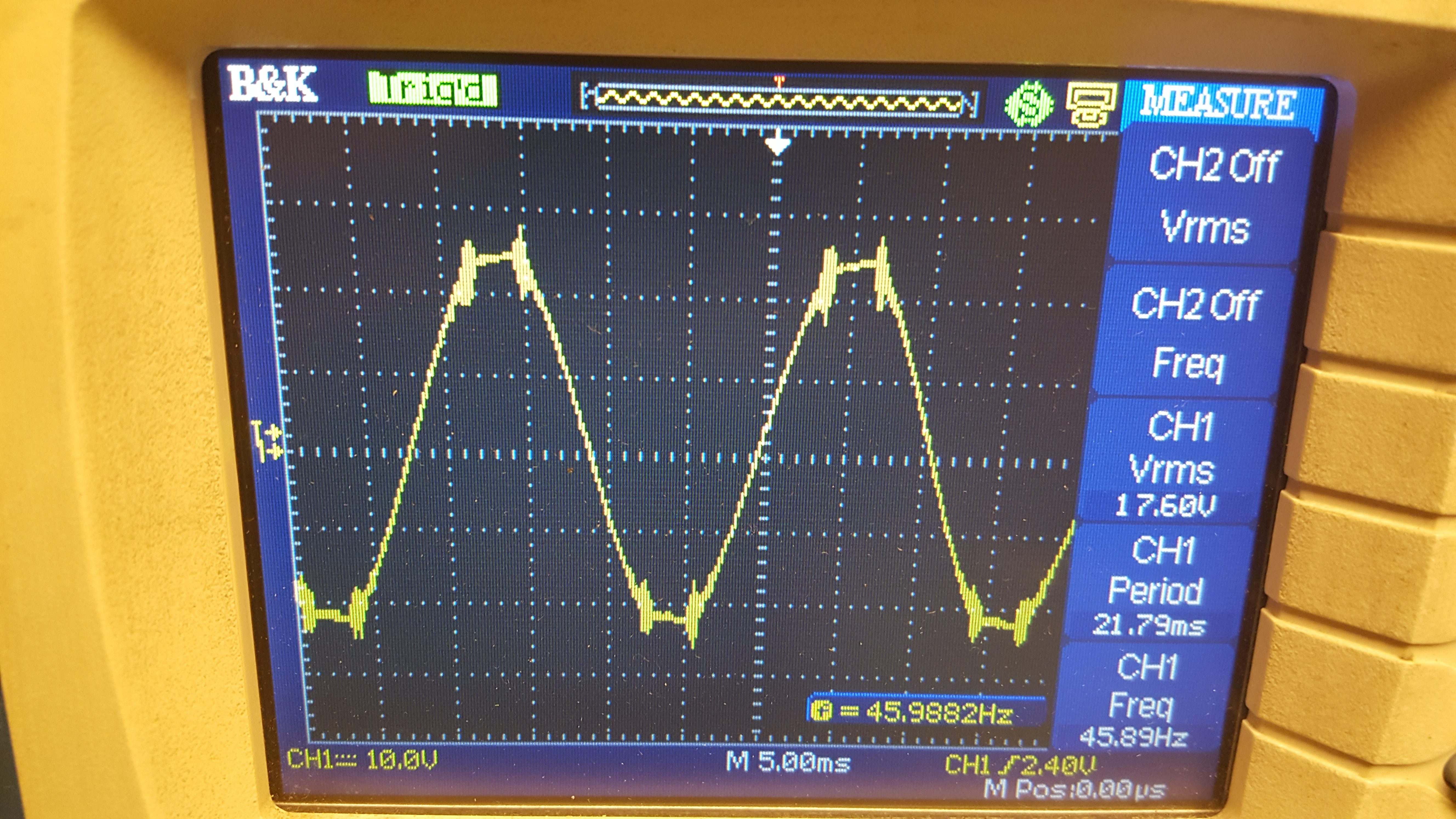
The plate amplifier was assembled and tested prior to completion of the woofer, with some additional modifications made to eliminate turn off thump. A great deal of attention was put on the ground wiring of the plate amp, particularly since the crossover boards used were not designed for a single ended supply resulting in what would have been the ground being +12V instead. In order to minimize noise issues, I used the potentiometers as a centralized grounding connection and ran a total of 4 18ga wires from the power supply to ensure a very low resistance path to ground centralized between all boards and connectors. Bench testing using a digital oscilloscope confirmed the 35WRMS of output capability into 8 ohms from the TDA7492 boards. The boards did exhibit an odd distortion on the oscilloscope as they approached their limit into a speaker load. The tops of the waveform had high frequency oscillation noise, but it was not audible on the test speaker. The reviews of the amplifier board seem to confirm that it’s not as good when cranked as other amps, so this is likely the cause of that perception.
An in room test was done before finalizing the woofer cabinet which confirmed plenty of gain to be driven from a PC soundcard output or other line level source.
Tips and Tricks
The woofer enclosure construction is really quite basic as far as speaker projects go, however the electronics assembly required is extensive and best left to those with existing soldering skills and a background in dealing with 120V connected power supplies.
For the Duratex finish using a smooth white foam roller, take care to look up some experienced instructions first. My attempt did not finish well, and I understand that slightly thinning the Duratex may have helped, as would using a second dry roller while wet to smooth the resulting coat. As it is now, I’ll need to sand and re-finish this box to get the results I was looking for.
Conclusion
This project is currently powering my bedroom system, sourced from a PC and running a pair of Dayton B652 speakers as satellites. The B652’s are wall mounted, and my current weak points. I run some EQ to compensate for the wall mounting and some room acoustics, and I also have plans to build compact 2 way micro satellite speakers in the near future.
Even with the lowly B652’s, the sound is enjoyable for relaxing on the bed and chilling to some music. The bass output from the woofer is very strong and really fills the space. It may not rattle the walls, but given its size and power efficiency it easily does what I wanted.


Pingback: MicroSat Speakers | The World of Wogg