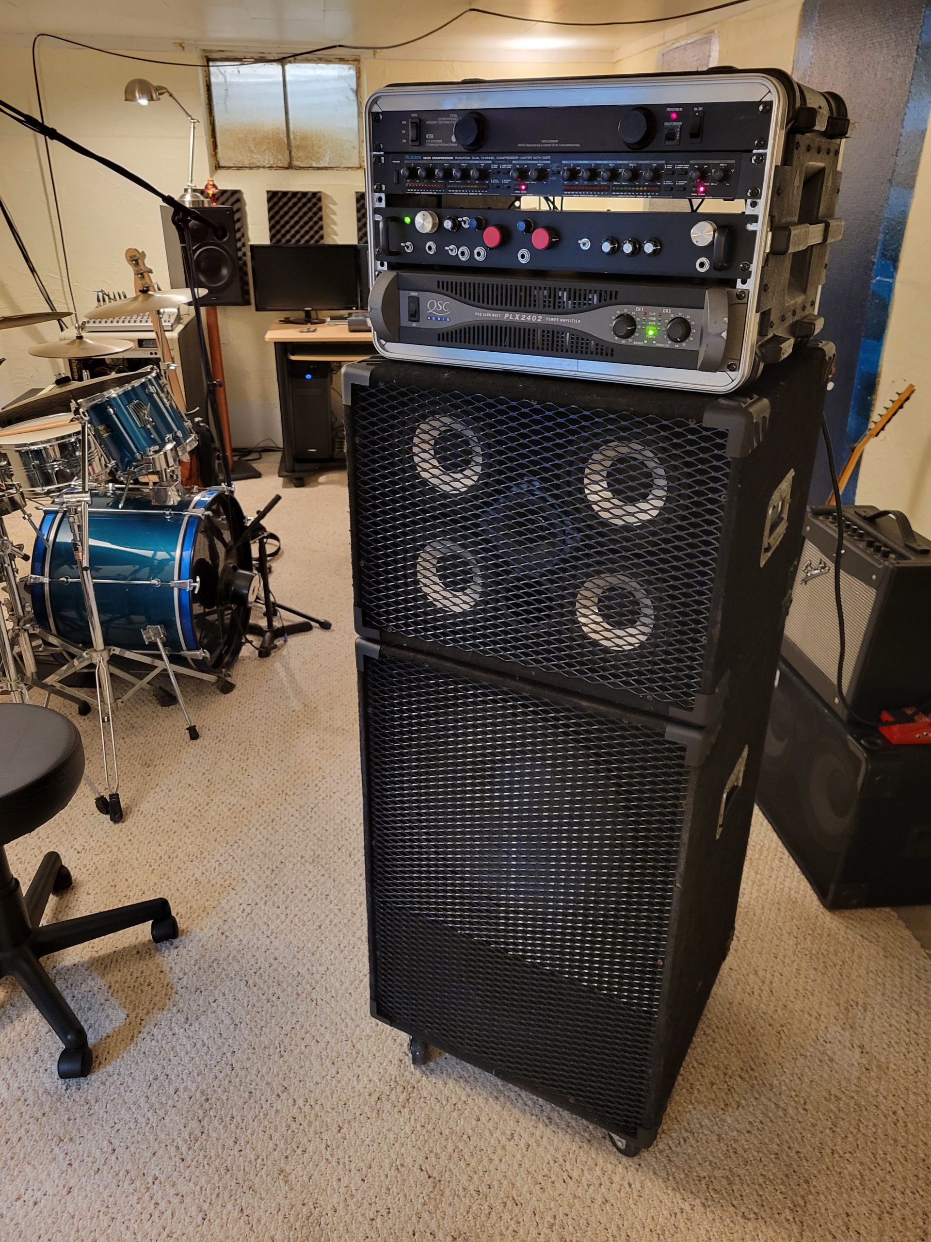
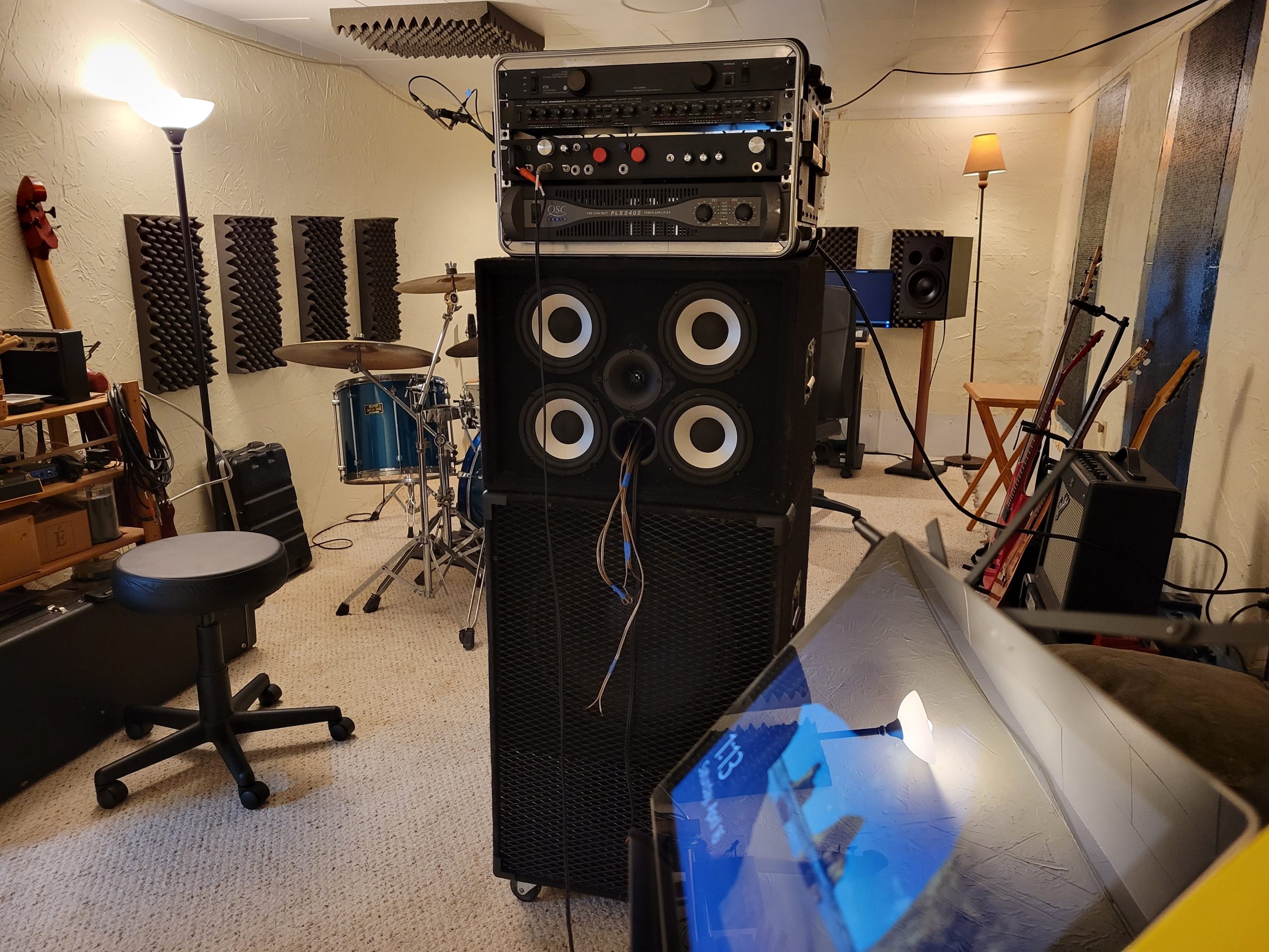
Tower of Power

Design Goals
This system was originally designed and built back in about 1998 when I became serious about gigging as a bass player and wanted a system worthy of the task. The goal at that time was to make it full range to support my playing style with a lower response limit down to 40Hz for the low E fundamental, and solid high frequency response to produce the transients and attack for some aggressive funky slap style bass playing.
At that time, I did not have the resources for actual driver measurements to base the design from and went with published sensitivities to match up the mids and tweeters. I originally utilized a Morel horn loaded dome but was unhappy with the amount of attack I could get and swapped it for an MCM bullet tweeter. The MCM woofers chosen for mids were left unfiltered, and a textbook 3rd order filter was implemented for the tweeter. This did just fine for over 20 years and a good 35,000+ miles of gigging. It worked well for bass but was obviously not accurate once you put some music through the system.
Fast forward to now… The tweeter filter lost a connection some time ago, taking the coil out of the circuit and leaving the tweeter more vulnerable to damage. It ended up burned out with an open voice coil and needed some refurb. With the currently available measurement and analysis tools, the opportunity arose to properly select a tweeter and design a filter for the mid and high cabinet.
Driver Selection
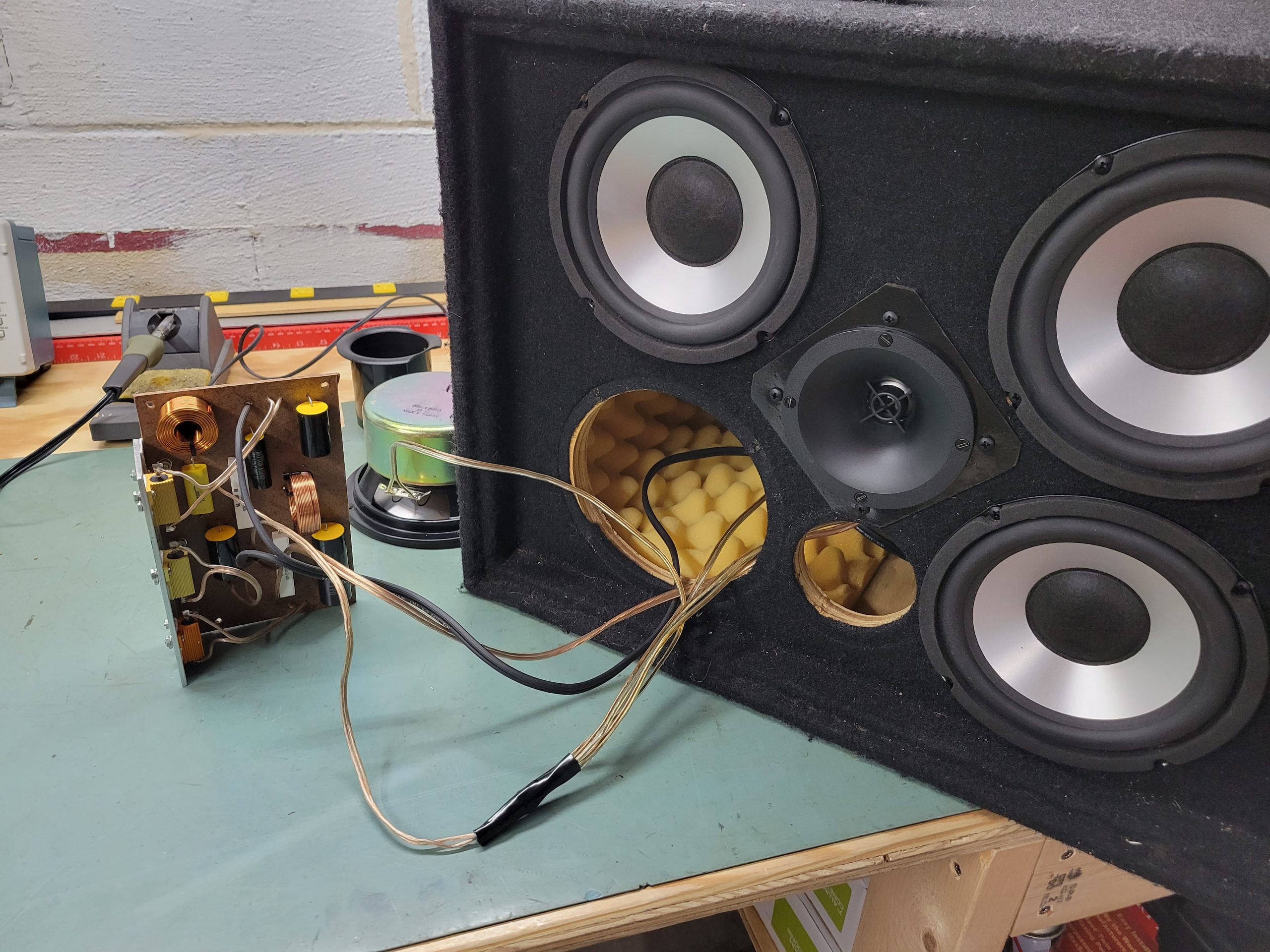
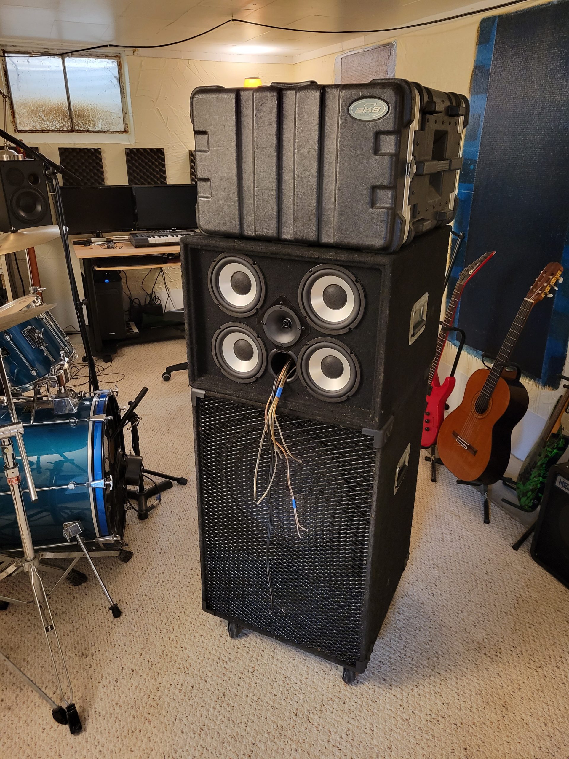
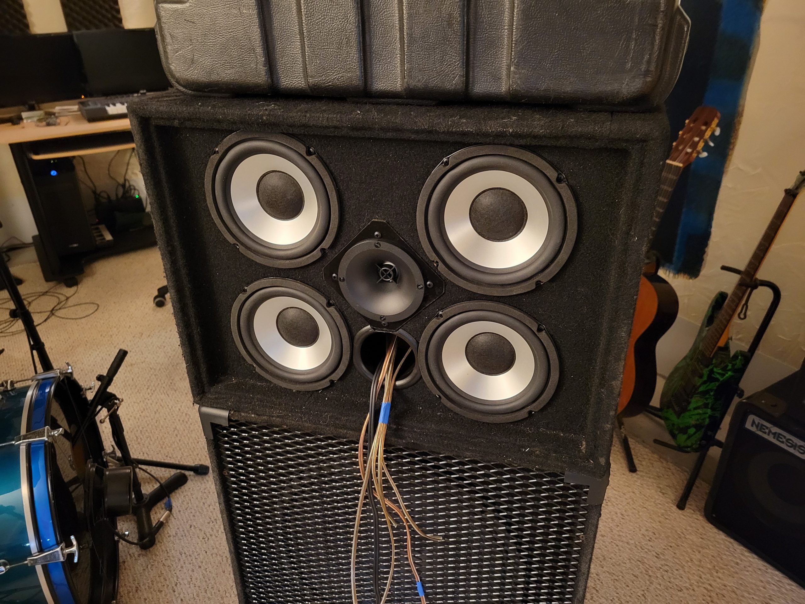
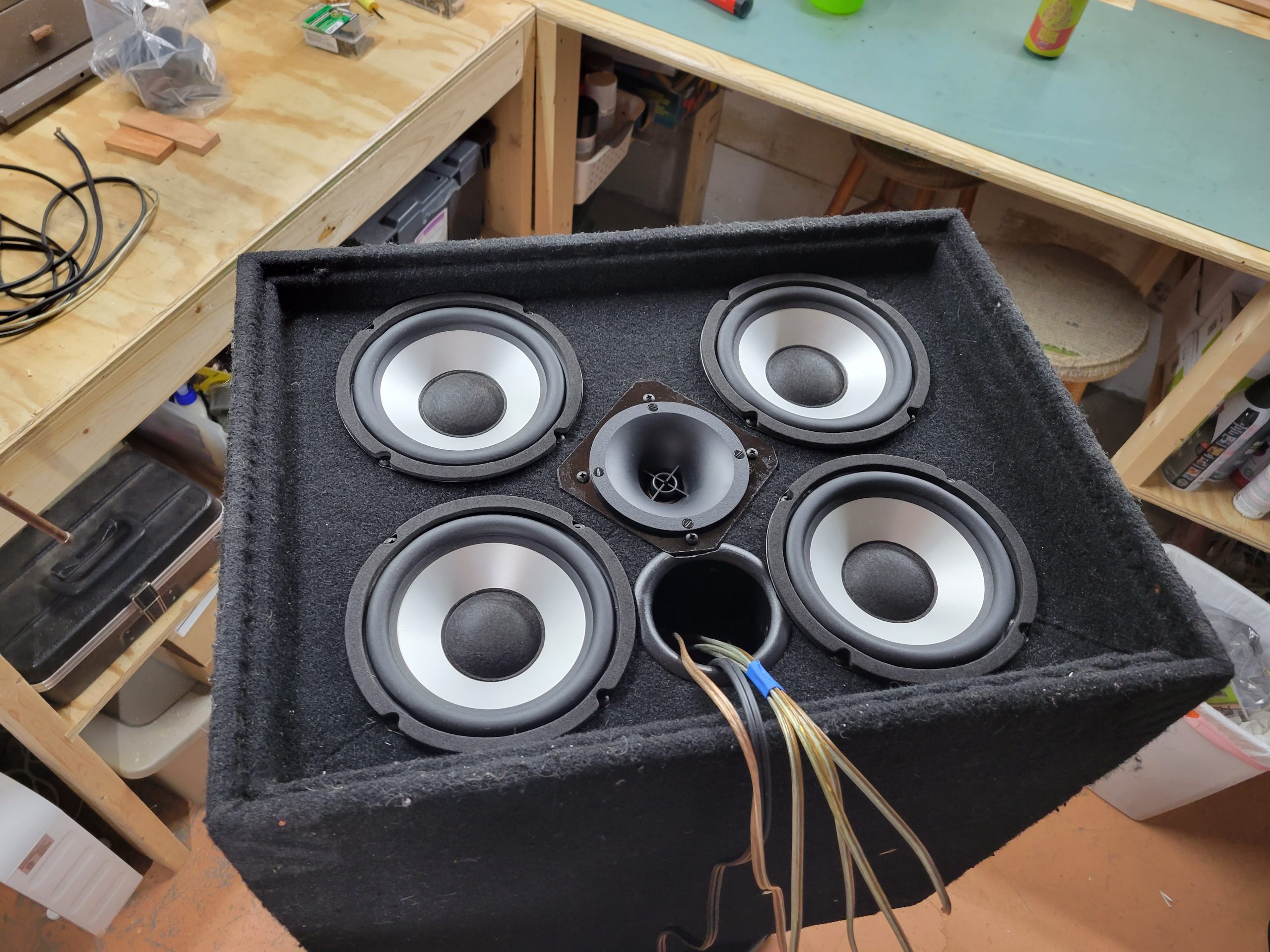
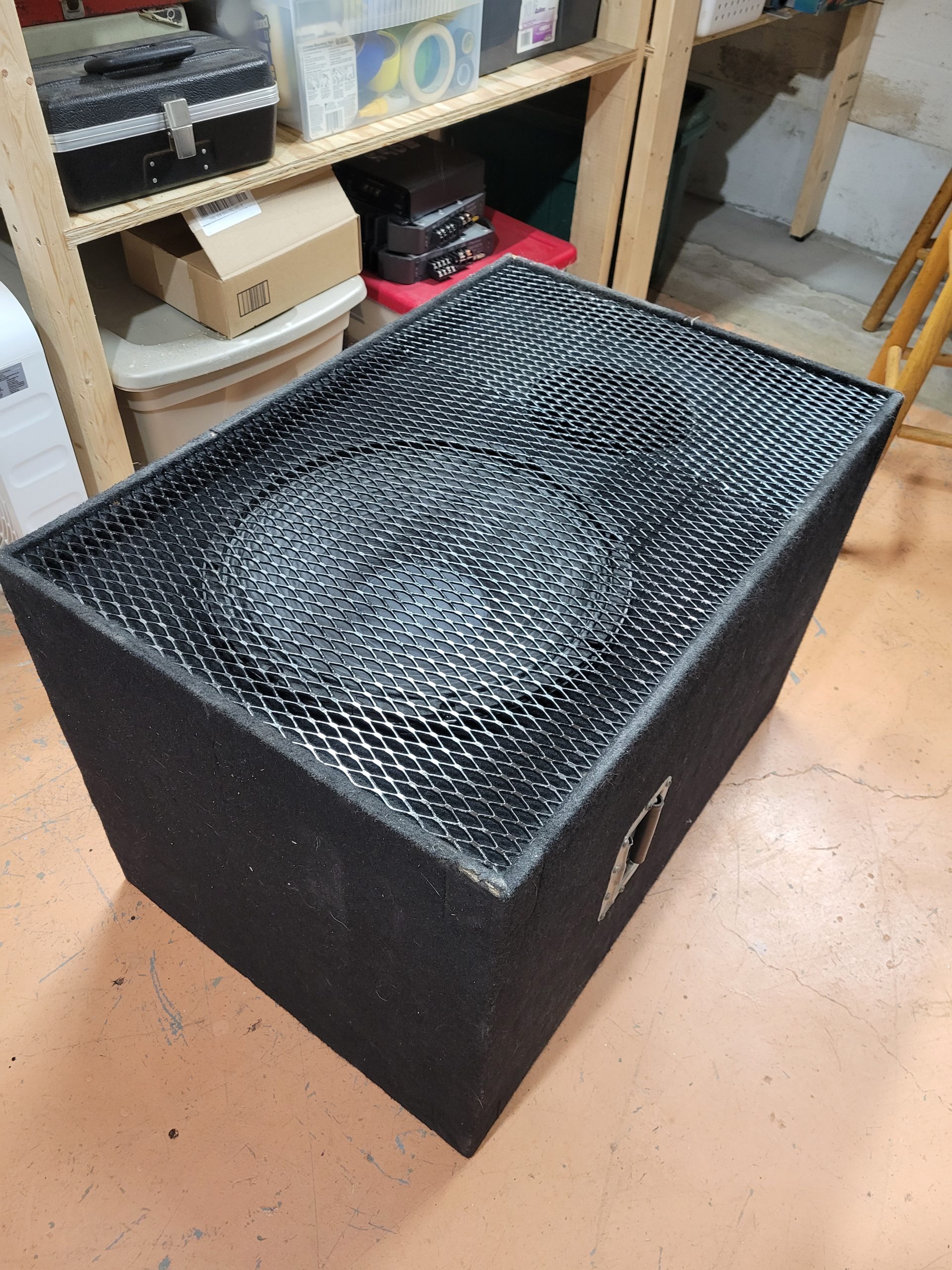
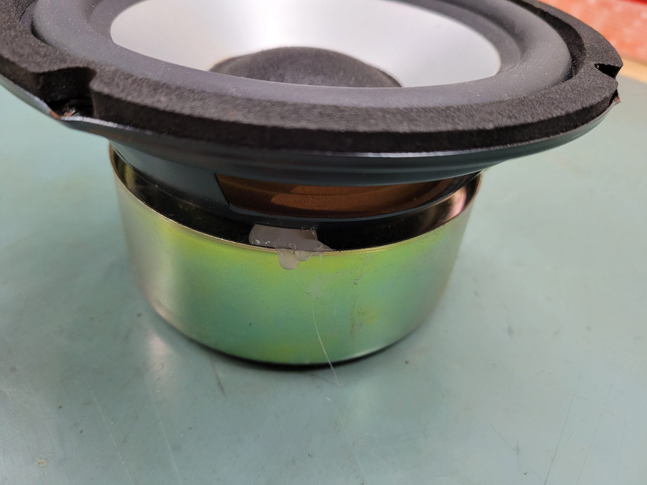
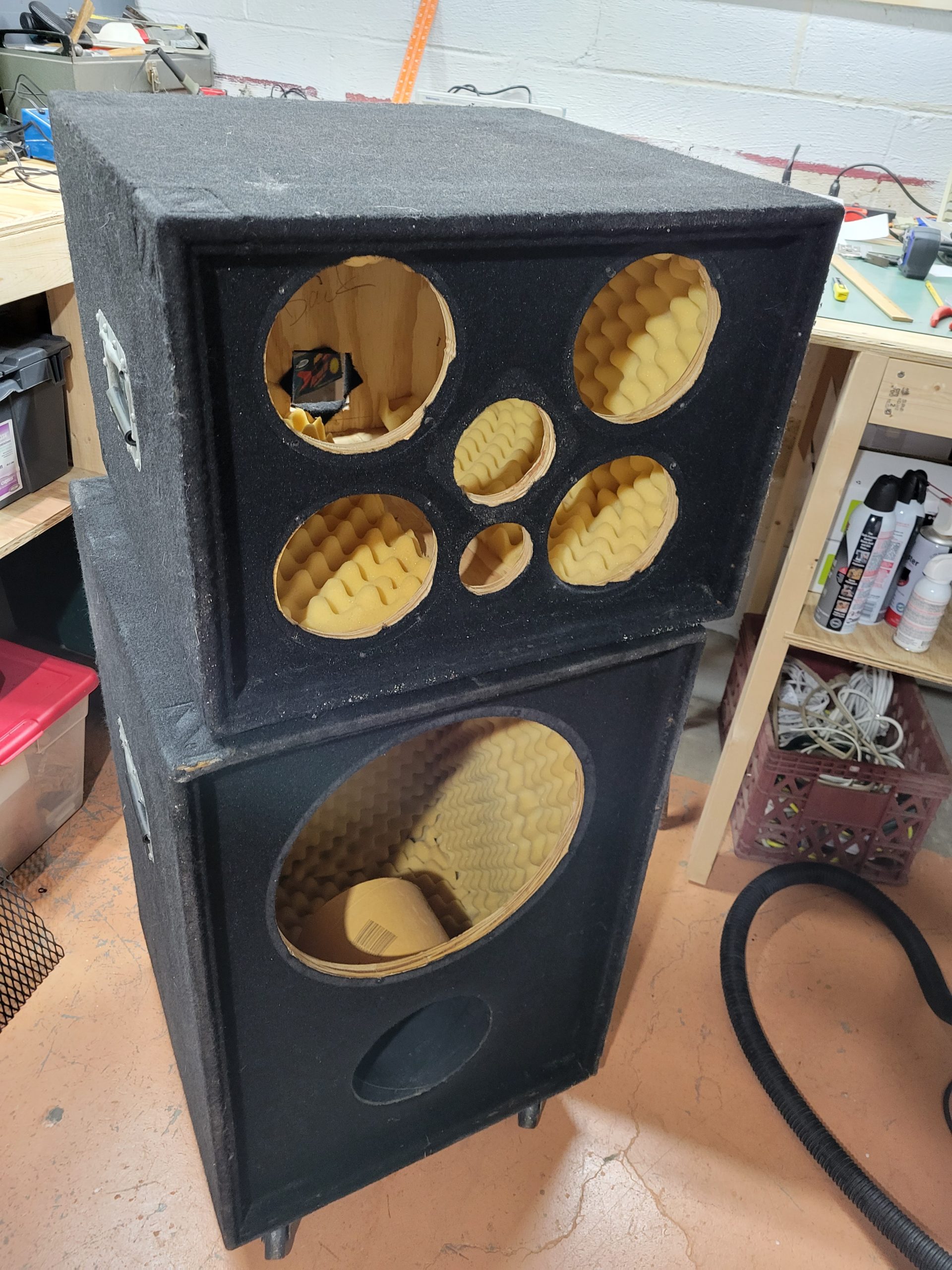
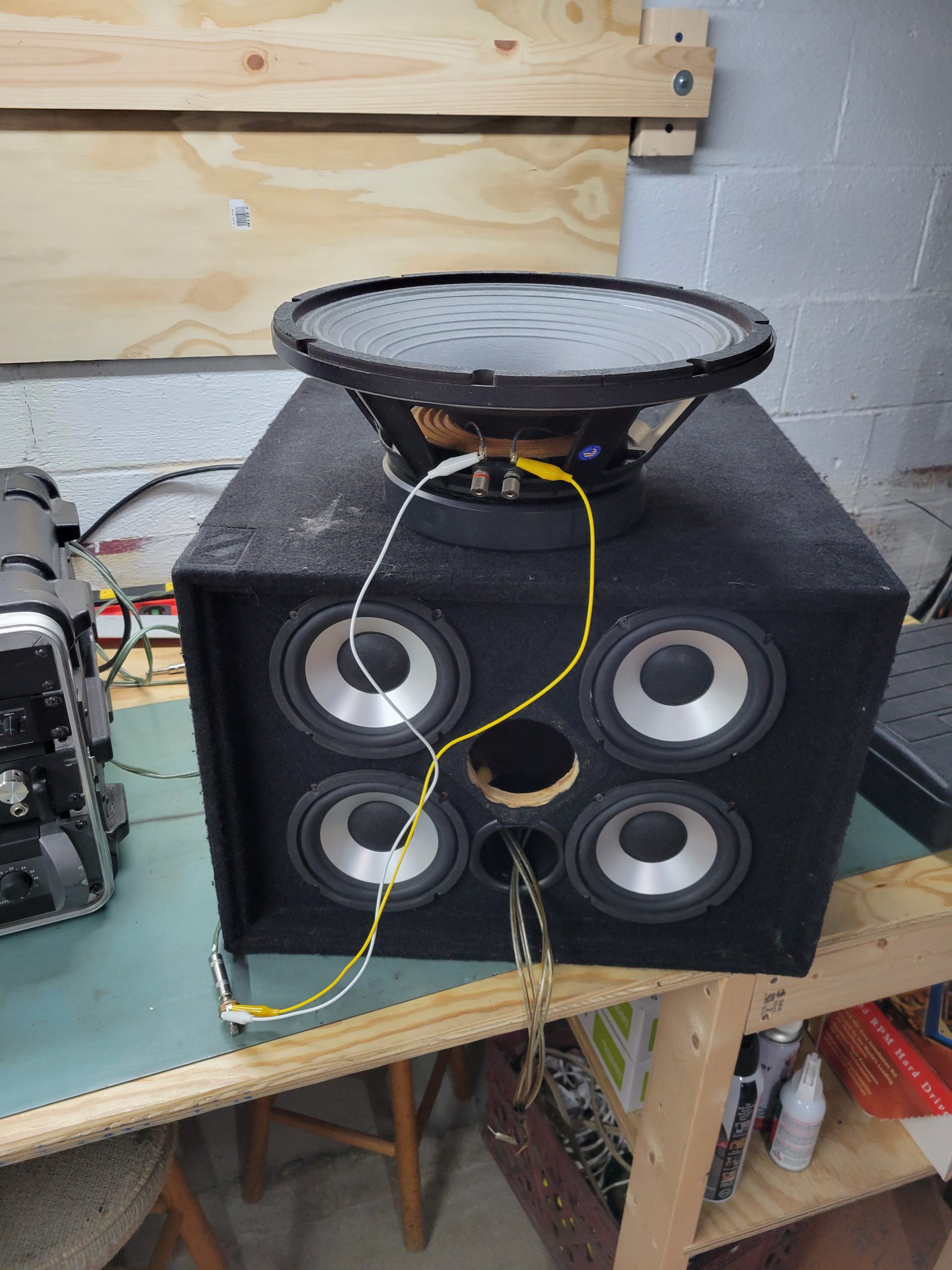
The drivers selected are largely maintained as is. The sub cabinet is an Eminence Omega Pro 15” woofer in 6.25 cubic feet tuned to 35Hz and is left as it was designed. The mid / high cabinet is a set of 4 MCM aluminum cone woofers, and a Peerless H25TG05-08 tweeter adapted to replace the old MCM bullet version. I would now go with a set of 4 pro driver mids in place of the MCM “HiFi” ones in this cabinet to get some more sensitivity, but again budget dictated that I use what I had.
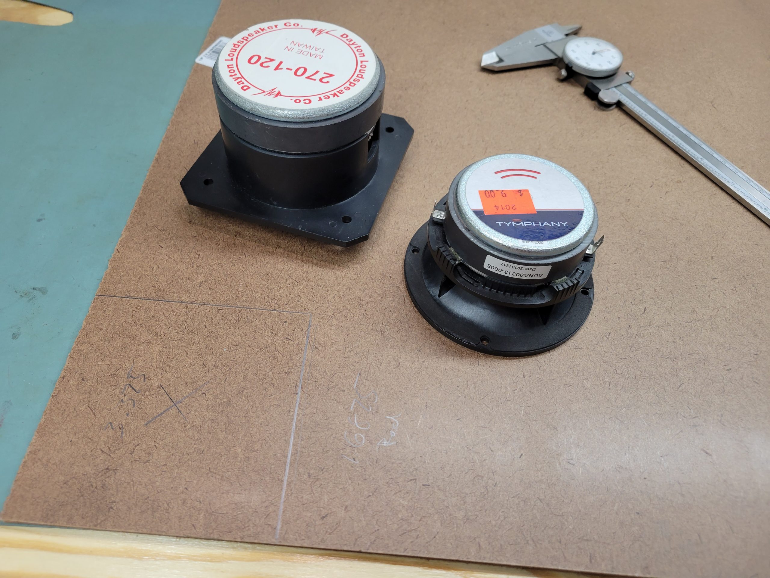
The tweeter selection was pretty much dictated by what I had on hand. I snagged a couple of these single high sensitivity tweeters at a DIY event thinking they would be excellent choices for a bass guitar amp top end, and the data sheet for this one doesn’t disappoint.
Enclosure Design
The enclosures were left as built long ago, out of ¾” ply and unbraced. If I was to re-build, I’d upgrade the ply and add bracing to the structure, but that was beyond the time and budget for now.

Both enclosures were modeled and designed using the OEM parameters at the time of build. The 6.25 cu ft sub enclosure modeled to deliver an F3 of under 40Hz, while the F3 of the mid / high cab was also modeled close to 40Hz. The mid / high cabinet was not critical however, as the design intent was to use with a 200Hz electronic crossover to the sub.
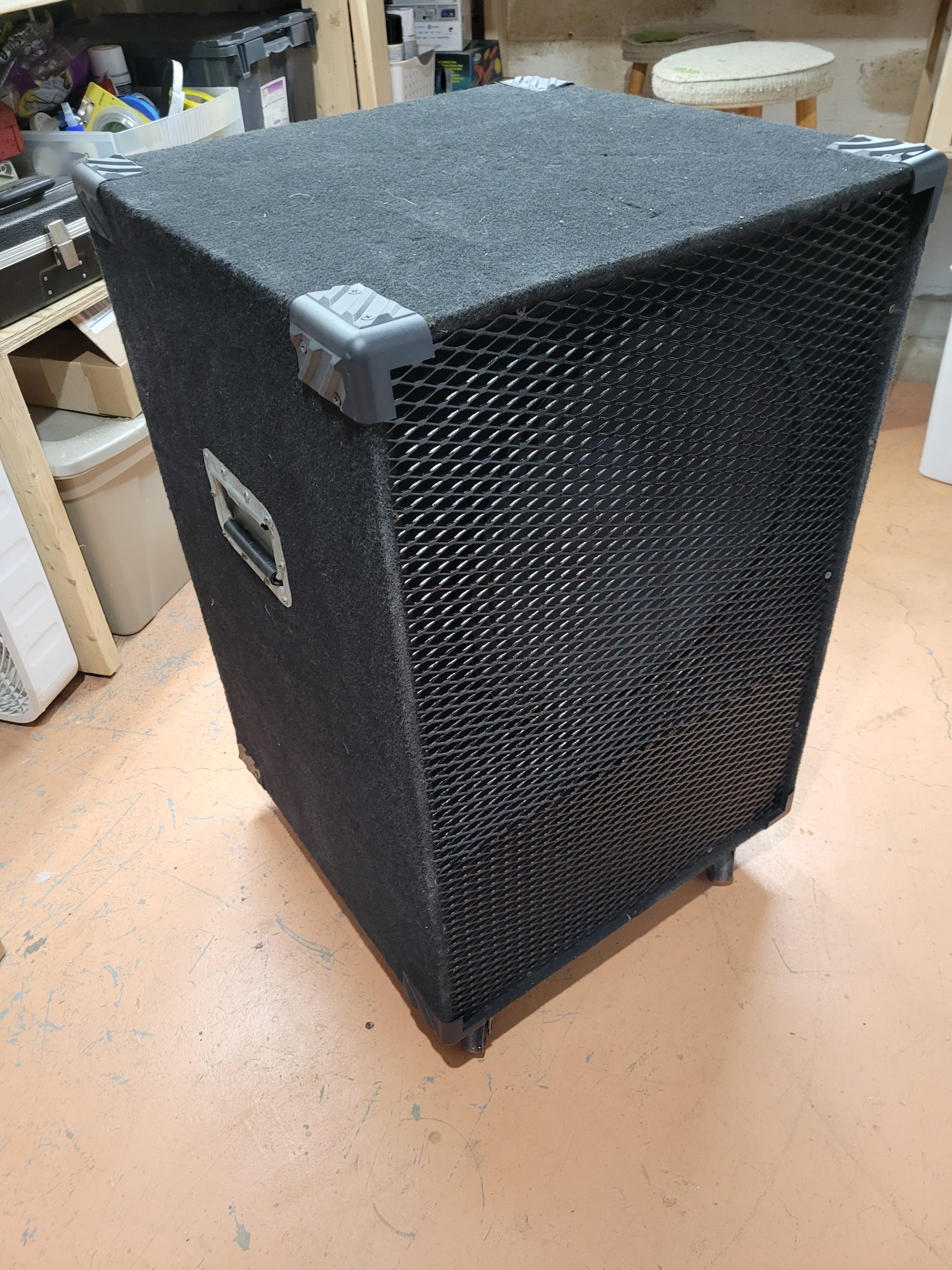
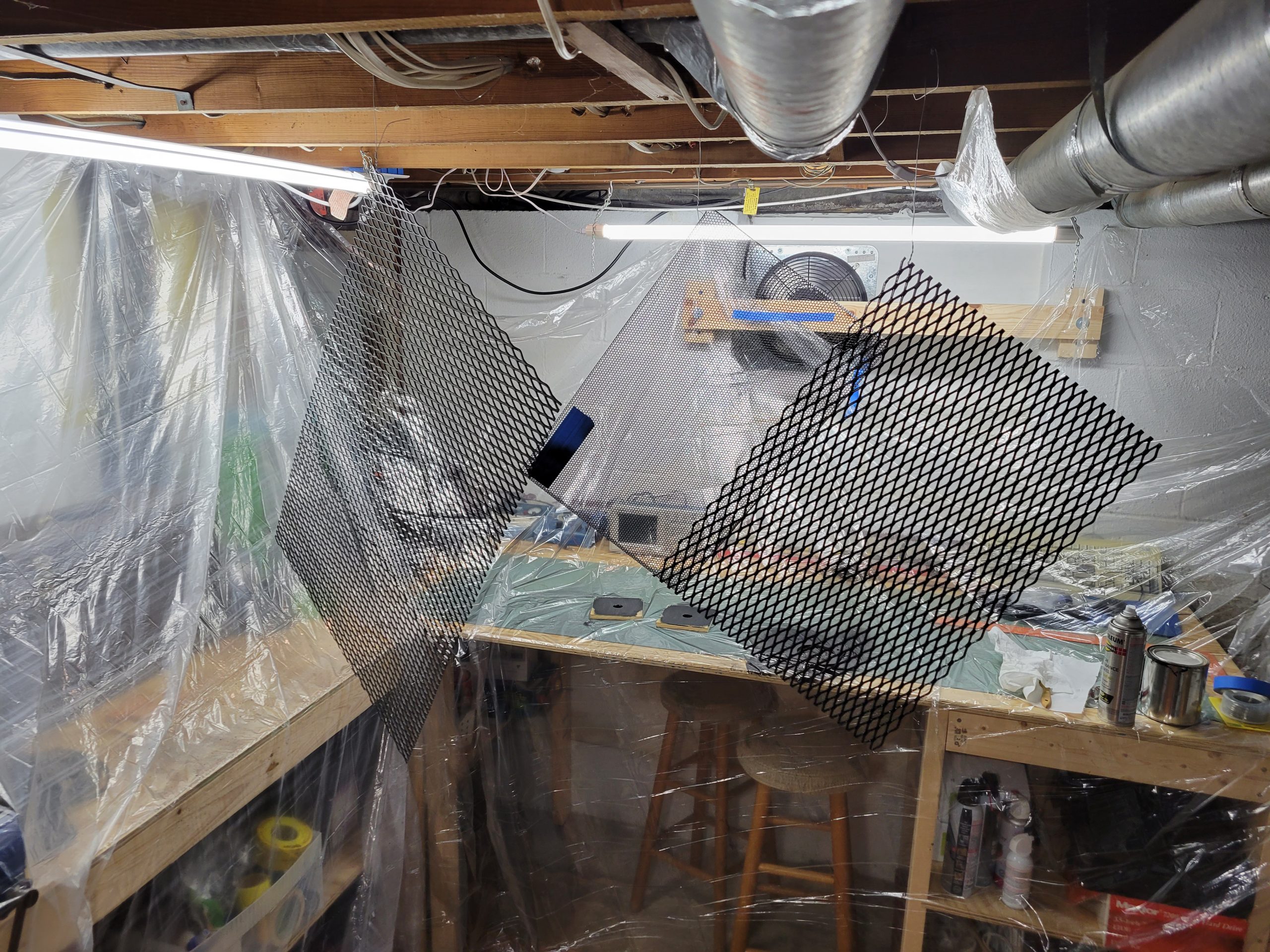
One of the main goals of the cabinets was to be road ready. Standard ¾” plywood was used as it’s far more durable than MDF, and the cabinets were finished with some cabinet grade carpeting, corner protectors, and an expanded steel grill embedded in the front to protect the drivers. After 20+ years of road abuse, the cabinets are still solid so I’d say that’s a win. The corners were all worn out, and the carpet covering has some dings, but overall these things are really tough.
Enclosure Assembly
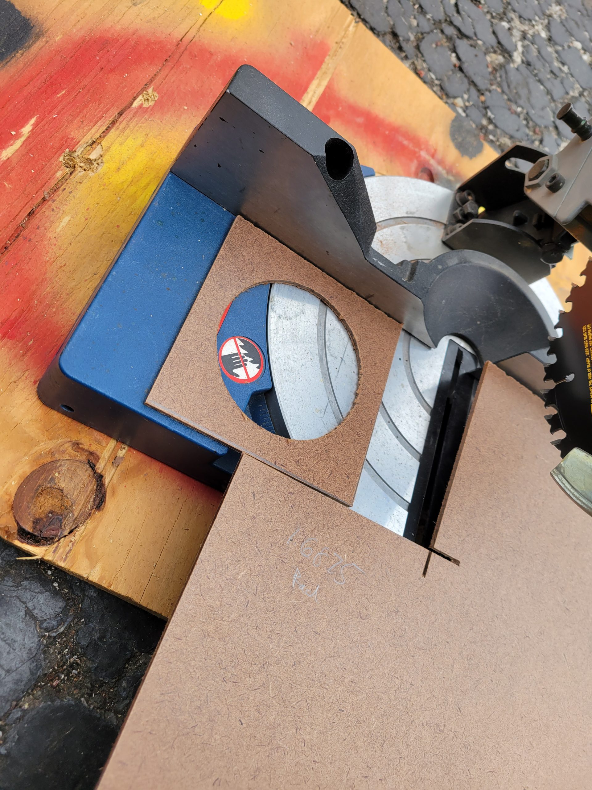
Nothing special here, trapezoids cut and used 3/8” rabbet all around with glue and screw assembly.
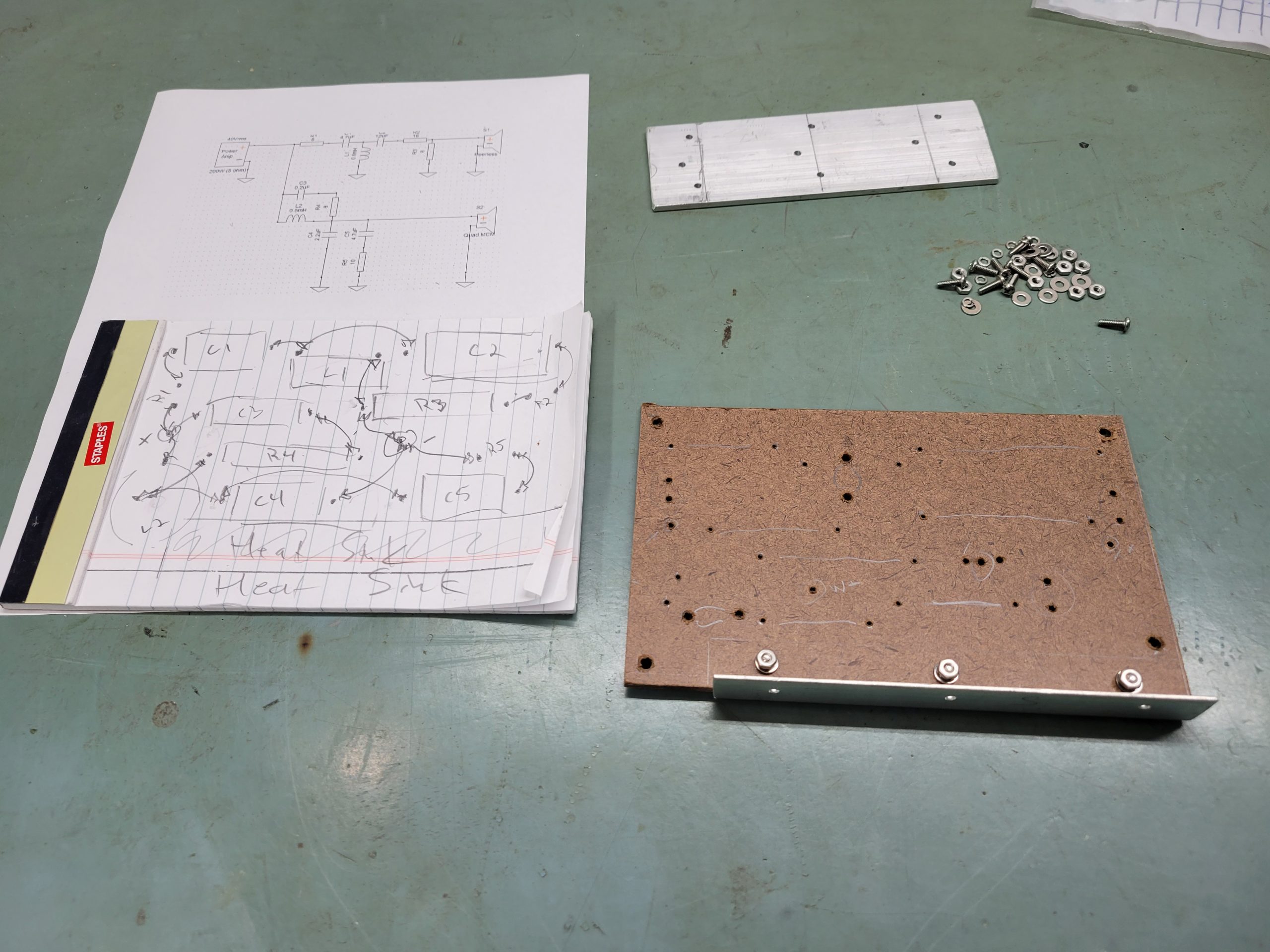
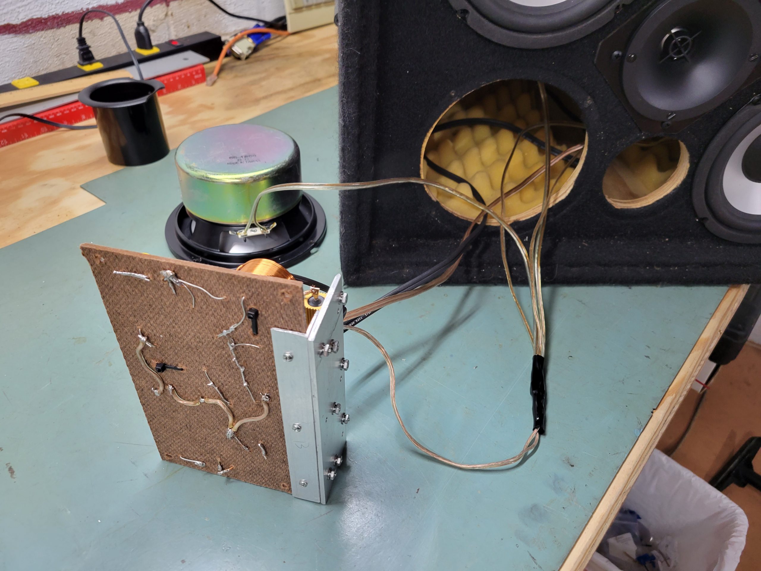
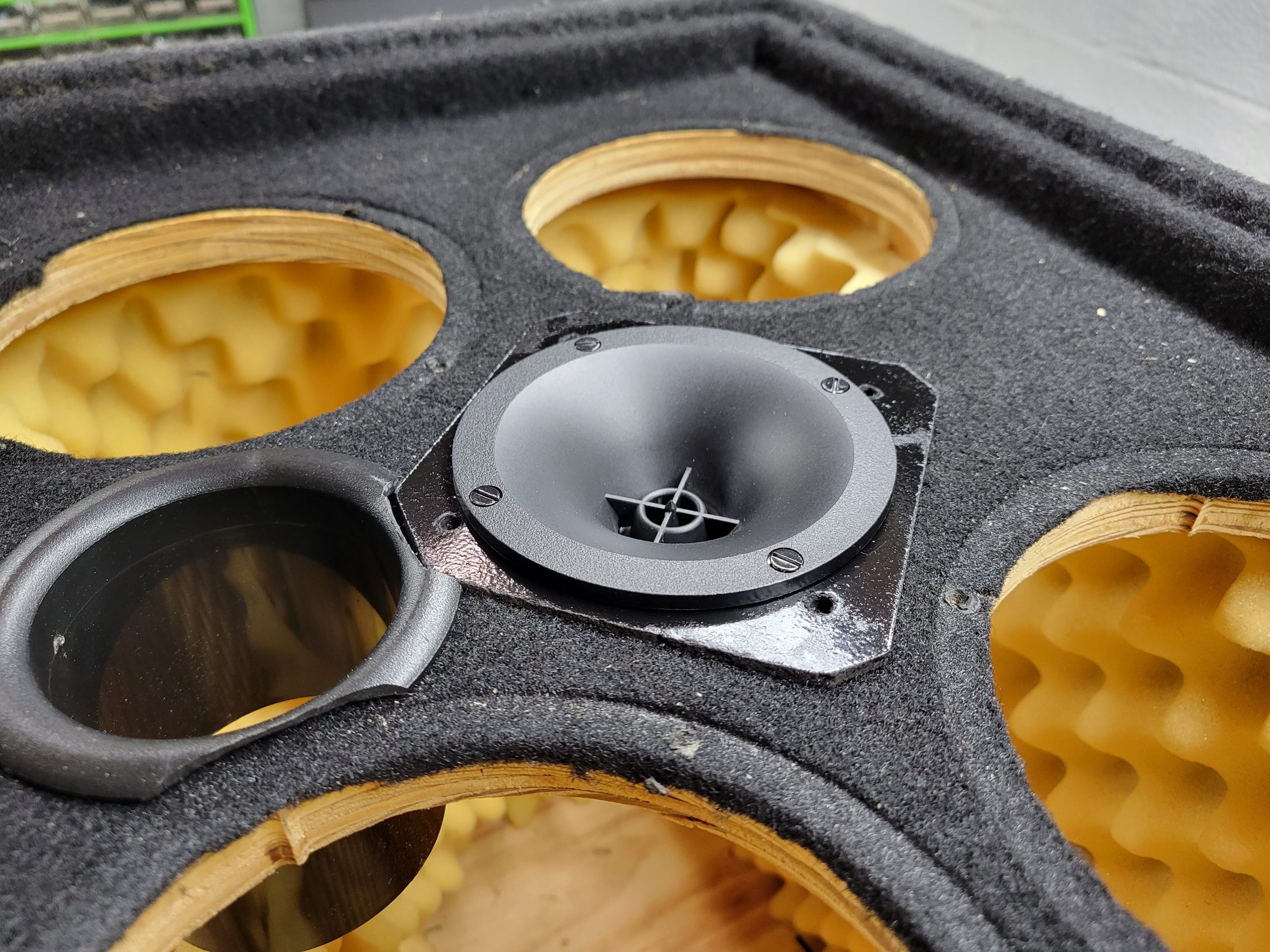
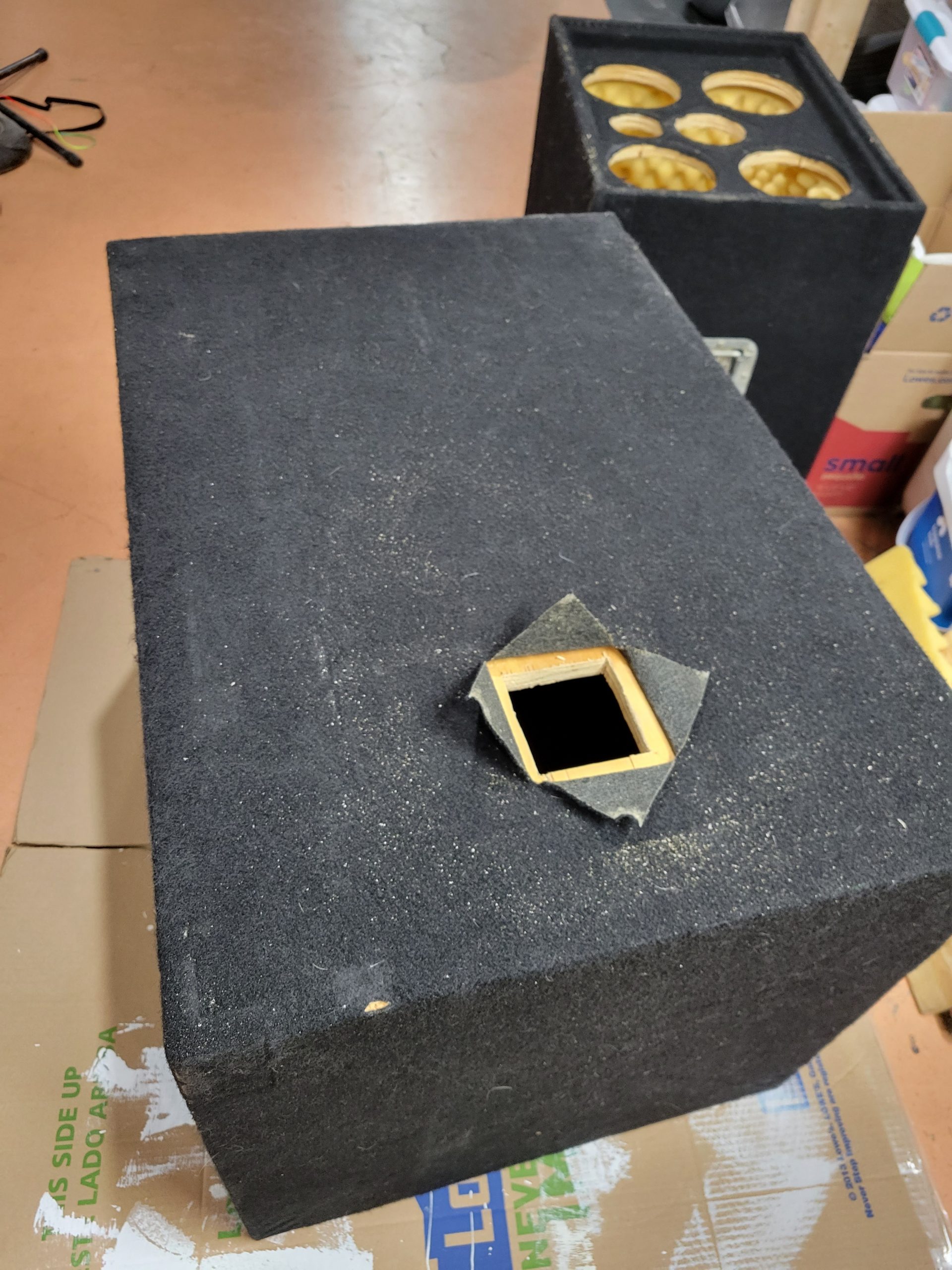
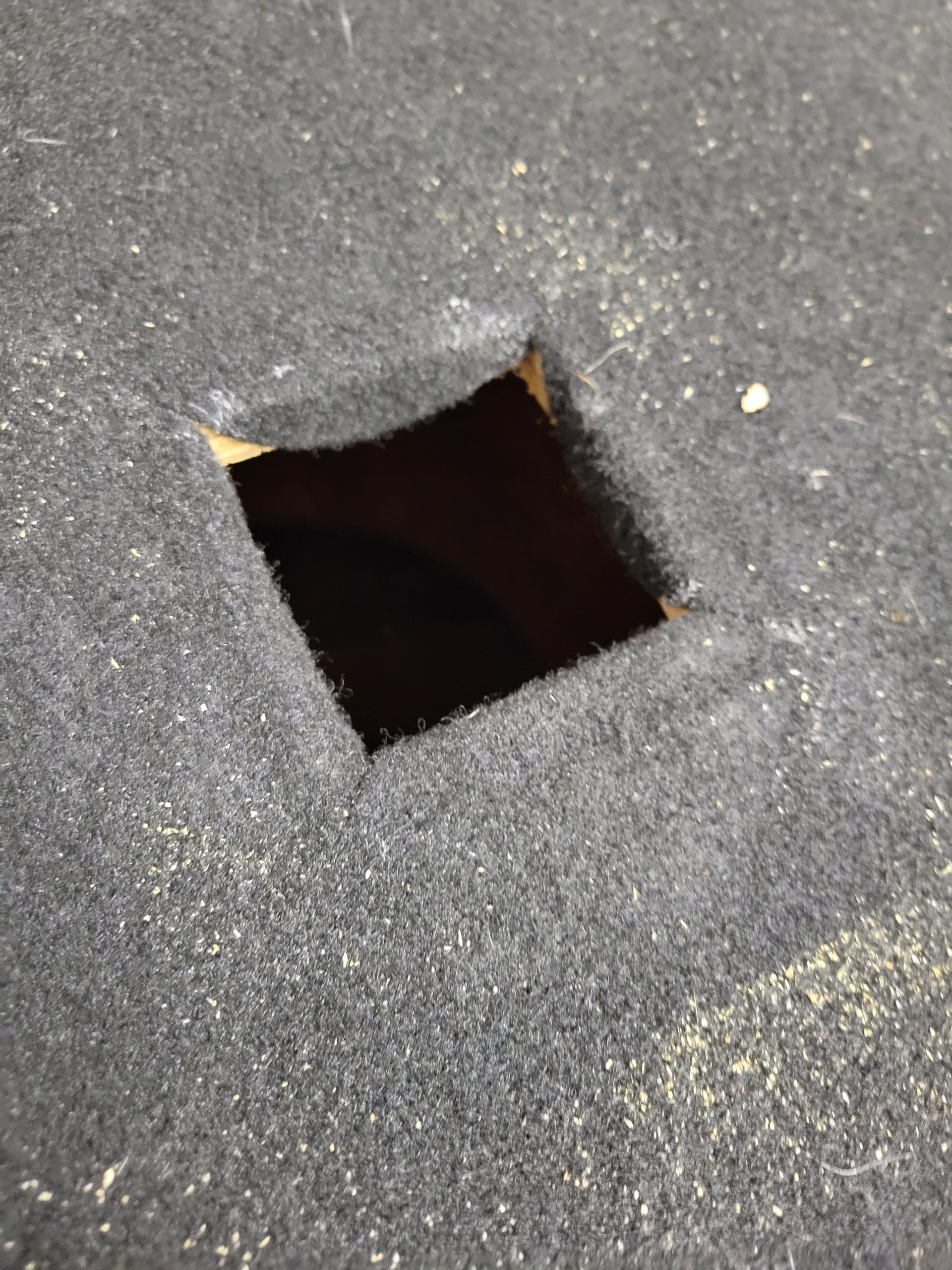
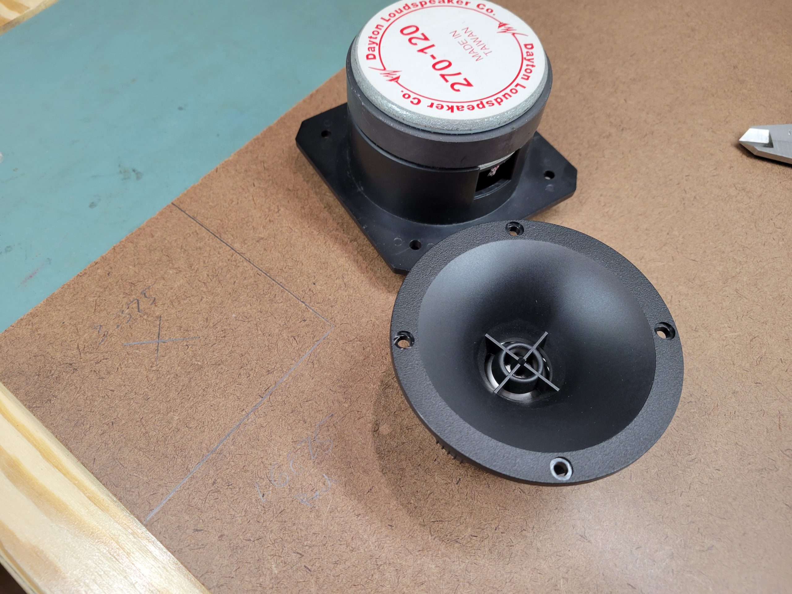
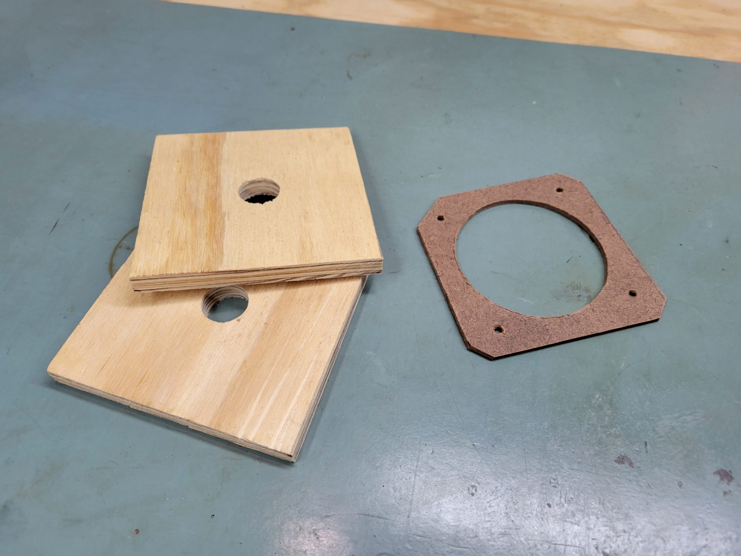
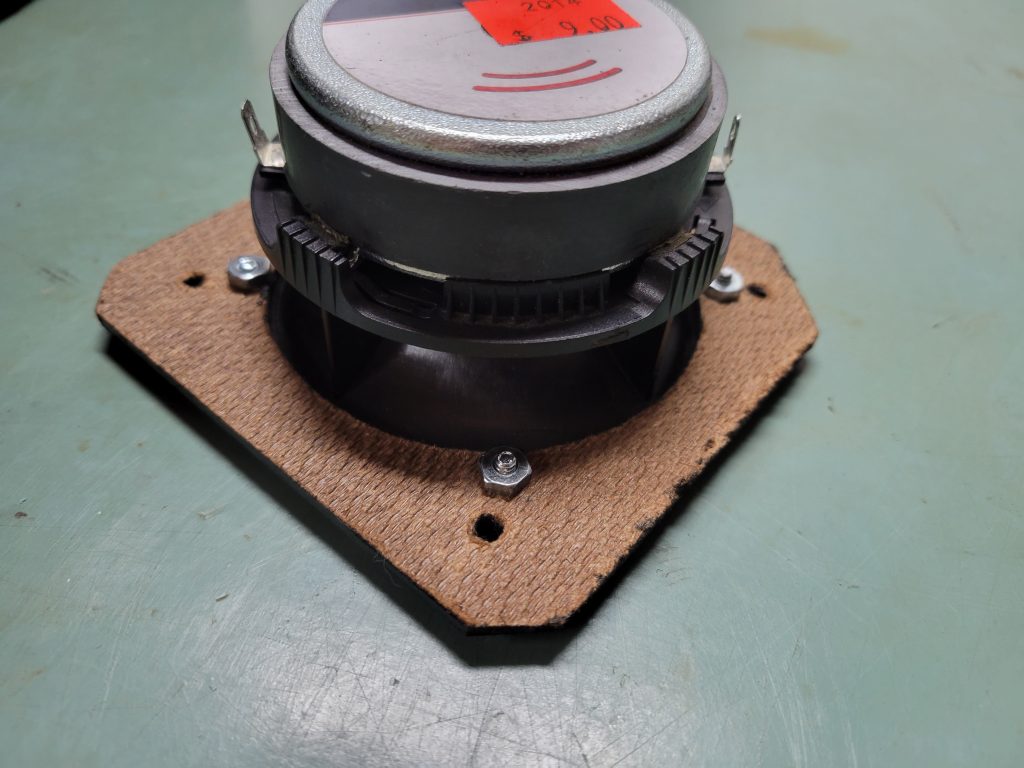
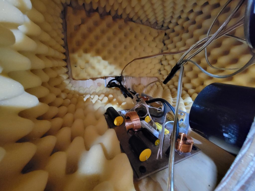
The replacement tweeter was significantly smaller than the old MCM bullet version, so some adaptation had to be done to seal the box. A HDF adapter was cut out to match the old tweeter mounting lip, with the new tweeter bolted to the adapter. The HDF being too thin to support screws, I used machine screws and nuts to assemble, then chiseled out notches at the edge of the hole in the baffle to clear the nuts. With the HDF painted black, it will hide behind the grill nicely.


Measurement Setup
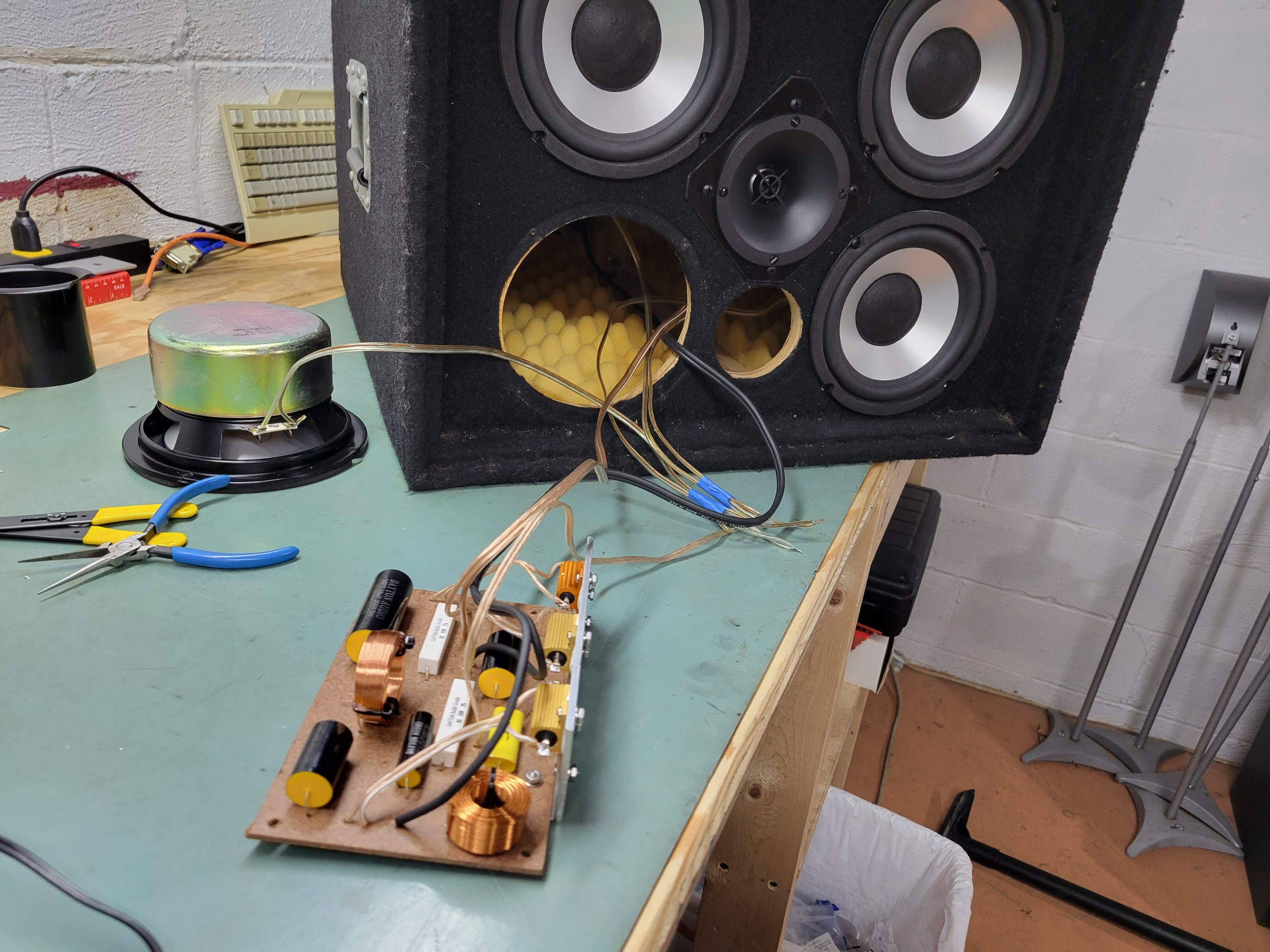
The design was approached as a standard 2 way system, with the 4 woofer array wired in series / parallel for an 8 ohm load and measured as a single unit. The measurement point was on axis with the tweeter about 1M out, with the symmetrical woofer array keeping the X/Y offset at 0 and only the Z offset as the variable to determine.
All measurements were taken though the full system, including the pre-amp and the 200Hz high pass built in for the high cabinet. The tone controls were set flat, and the compressor was bypassed to keep the data clean.
That was the measurement theory anyway, once the data came in it was apparent that the woofer array doesn’t appear as a single source at all once the wavelength of the sound becomes smaller than the distance between woofers. With 7.5” smallest dimension between woofers, that means comb filtering kicks in at about 1.8kHz and complicates the view of the crossover region. The comb filtering was very much dependent on the measurement point, so in order to properly design and model the crossover I would have to deal with some crazy data from 1.8k to about 3k. That limited my ability to really see what was going on in the region, and instead of shooting for a solid phase match and reverse null my goal was switched up to making sure the tonal balance on either side was solid.
Crossover Design
High Frequency Cabinet Update
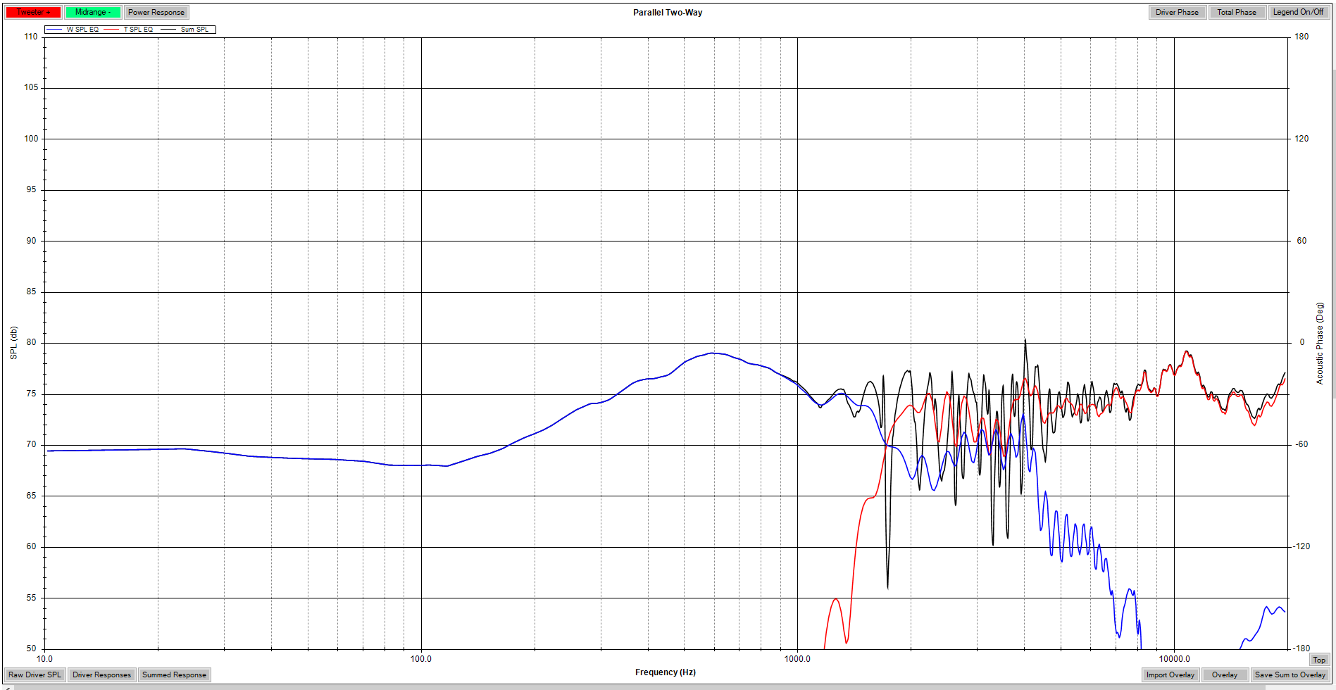
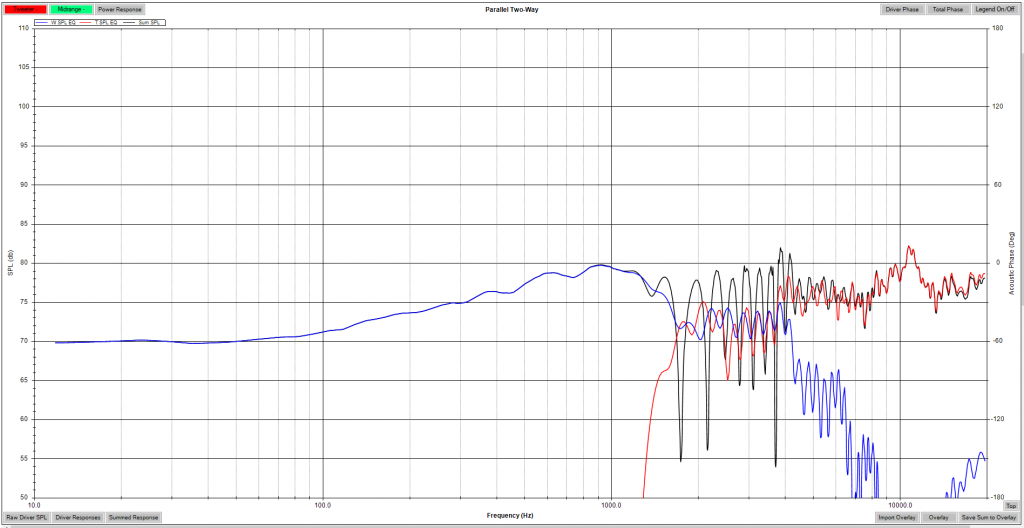
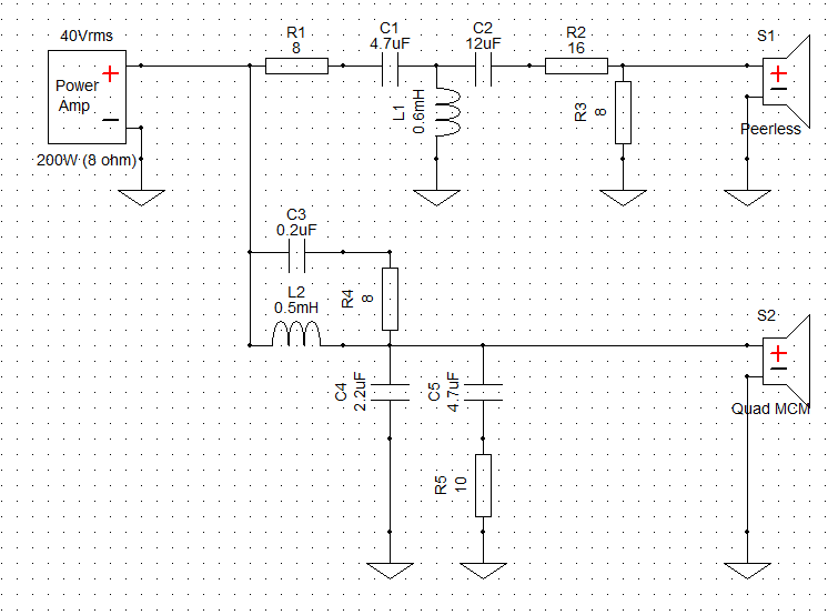
Using the on axis measurement data, a filter was drawn up aligning the mid and high levels and keeping the crossover region match as good as it could be determined with the less than optimal measurement data. The MCM woofers are by far the weak spot, as they are not intended for pro audio and have lower sensitivity than needed. These mate with the incredibly sensitive tweeter, which needs a whole lot of pad to bring down to level. Additionally, the 4 woofer array shows a large amount of gain below about 500Hz where the woofers couple properly, making the mid range area around the crossover point relatively weak.
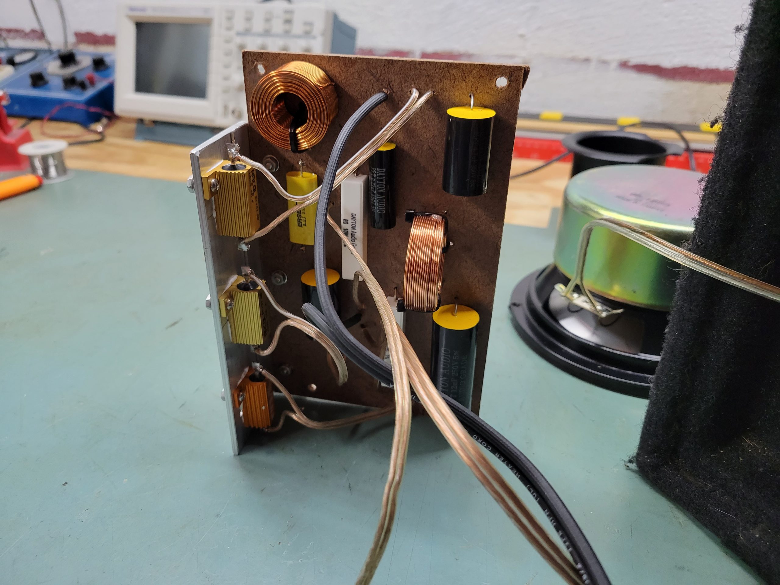
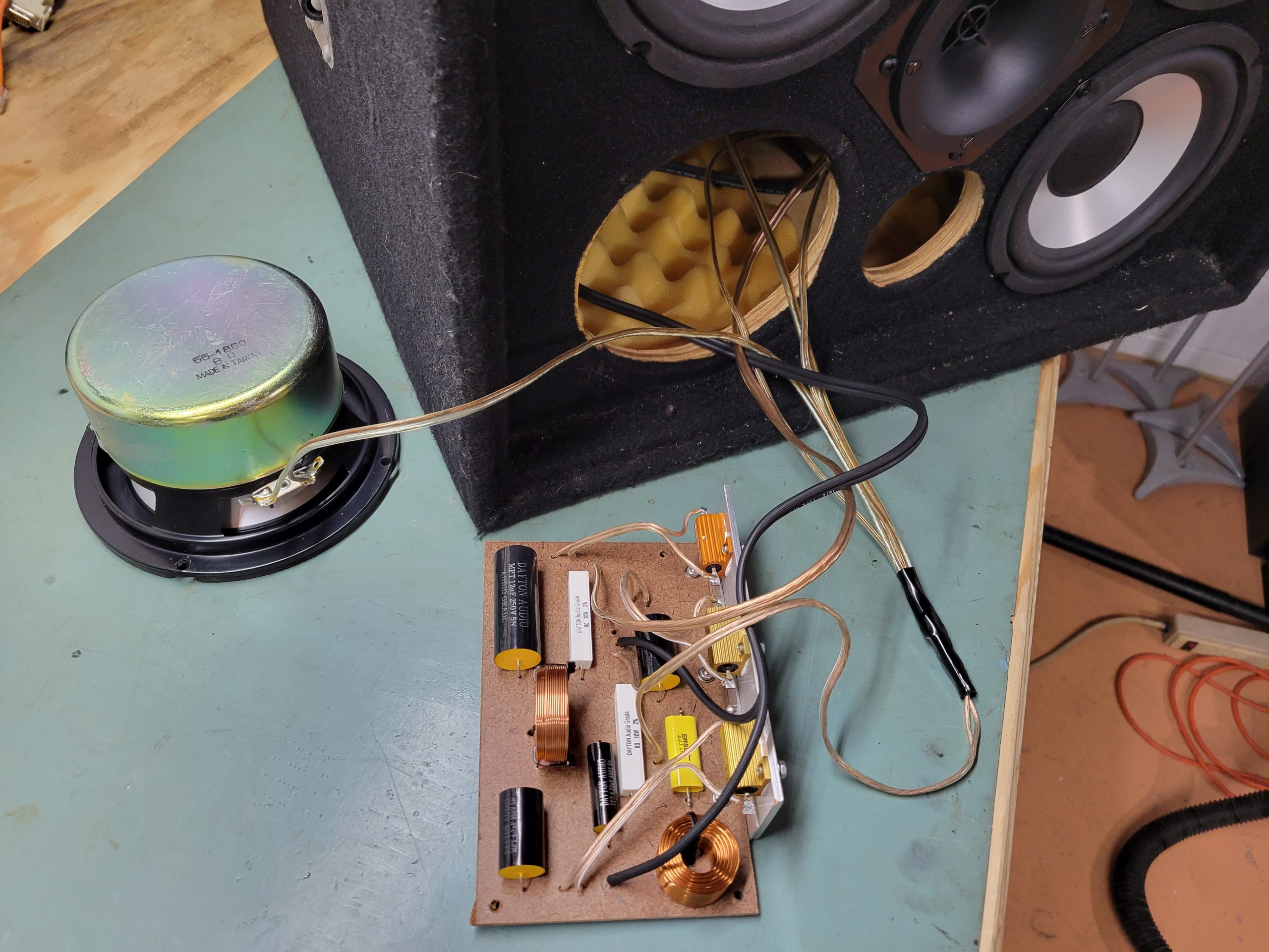
The filter was started using one of my typical topologies, a third order electrical for the tweeter and a second order for the woofer(s) using a damped tank capacitor across the inductor to suppress the breakup further. Heavy padding on the tweeter was used both before and after the network to shape the curve appropriately. I also found the MCM woofers had a really high inductance value, making the filter ineffective without the use of a Zobel network parallel with the voice coils. Using WinPCD, the values were tweaked until an acceptable balance and curve was found, ignoring the deep comb filtering nulls and looking at the general average.
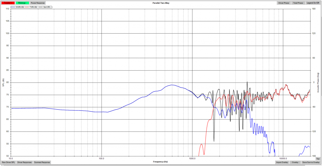
In order to help validate the filter selection, I made some additional measurements in an attempt to see what is going on behind the comb filtering. I made 3 measurements across the front of the system and utilized the calculator function in VirtuixCAD to create a single RMS FRD file. This was pulled back into the same crossover, which still showed a similar output. Figuring that’s about the best I could do with the data, I went ahead and moved forward with the design.
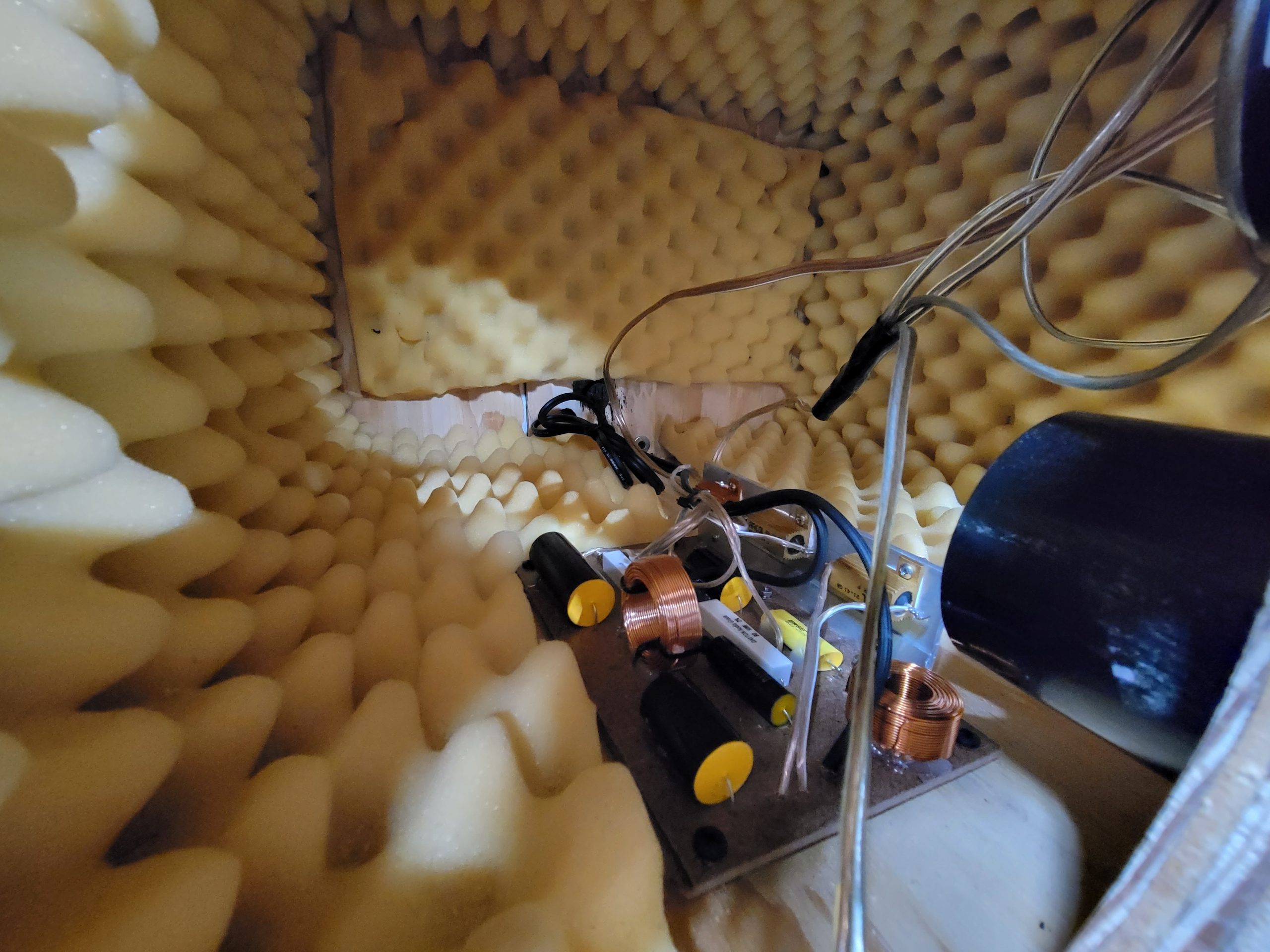
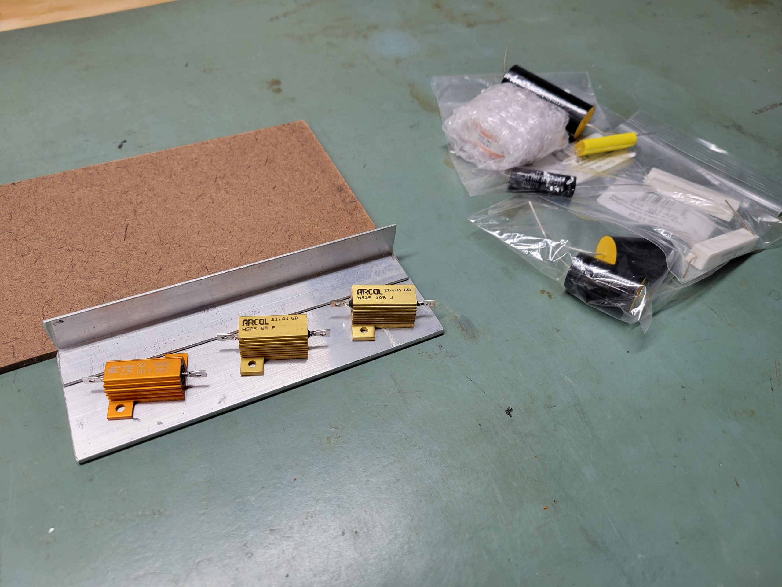
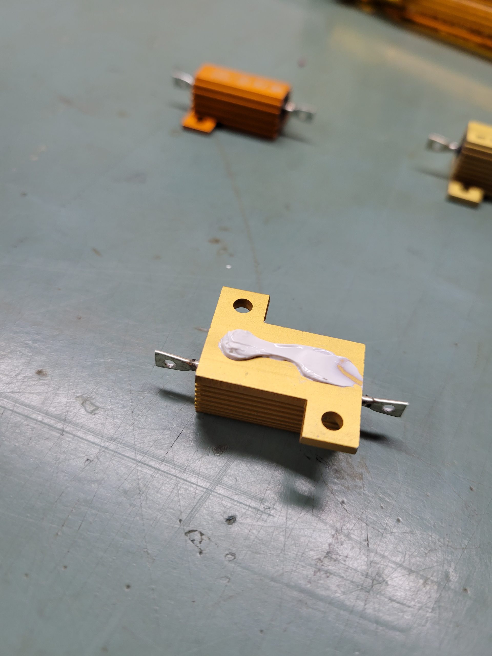
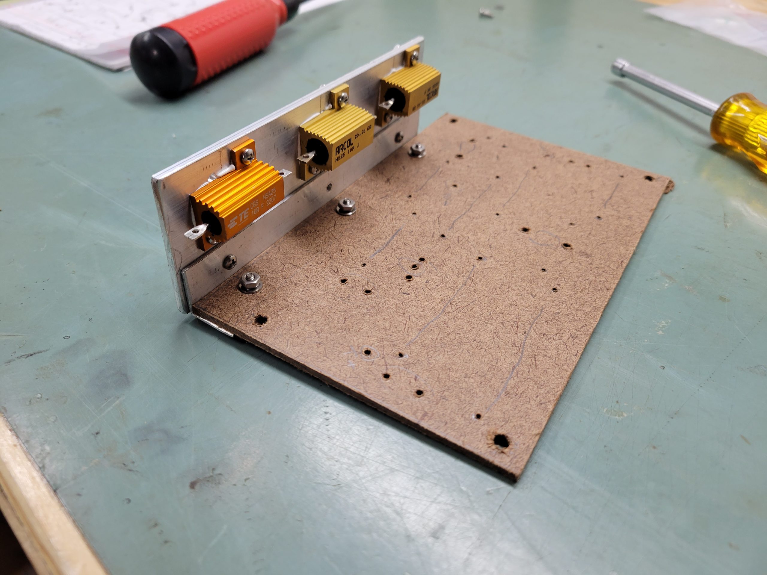
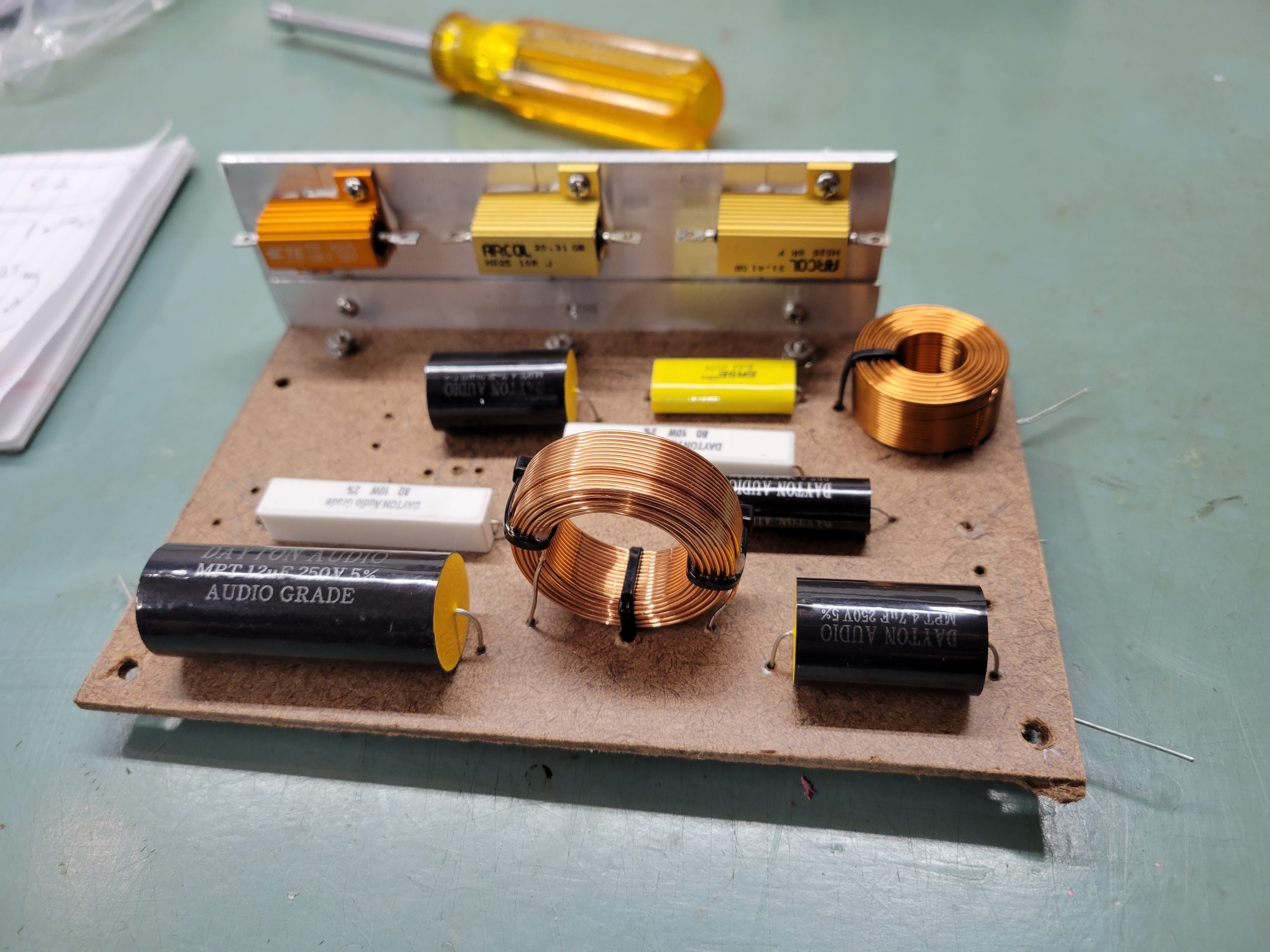
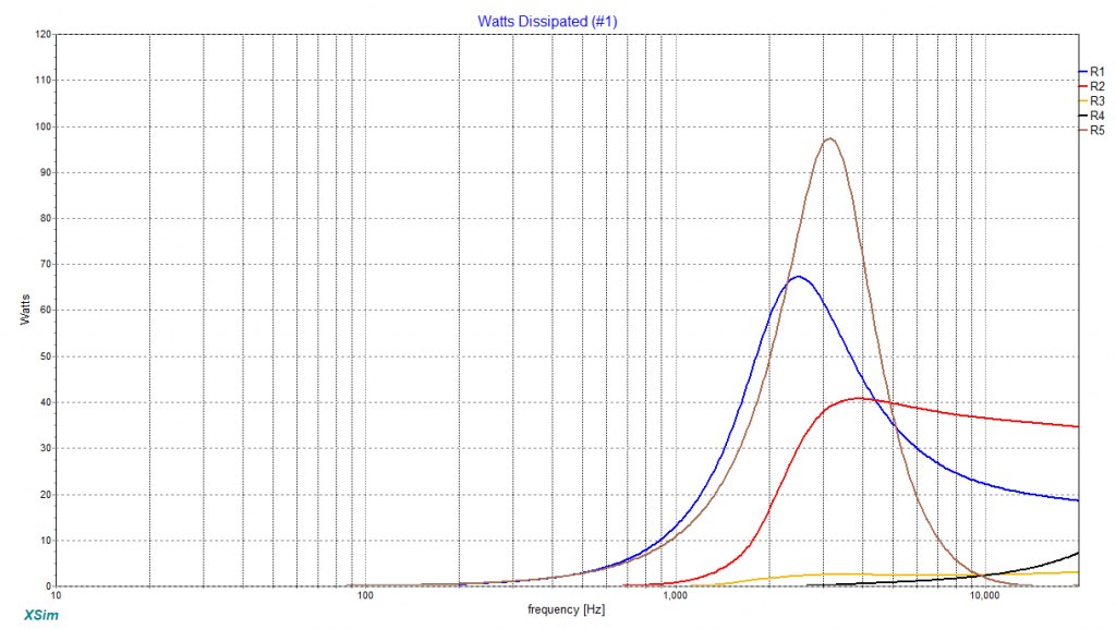
The filter was simplified and pulled into Xsim for validation, which also showed the same decent results. The power on the resistors was graphed and an immediate concern. The series resistors in the tweeter network and the woofer Zobel resistor are all showing very high power requirements when hit with the capability of the pro audio amplifier to drive them. However, Xsim does these calculations based on a full voltage sine wave sweep, which is not going to be happening in practical application. So even though a good 200W is possible on the Zobel resistor, that occurs around 3KHz. In real life application, content at that frequency will be sparse and dynamic so that full power is not expected and when it does hit, it should be very transient. In order to deal with this power, I opted for 25W heat sinked resistors, and use an aluminum bar to mount the resistors for full power capability. That should allow long term use at high levels without failure.

Electronic Crossover to Sub
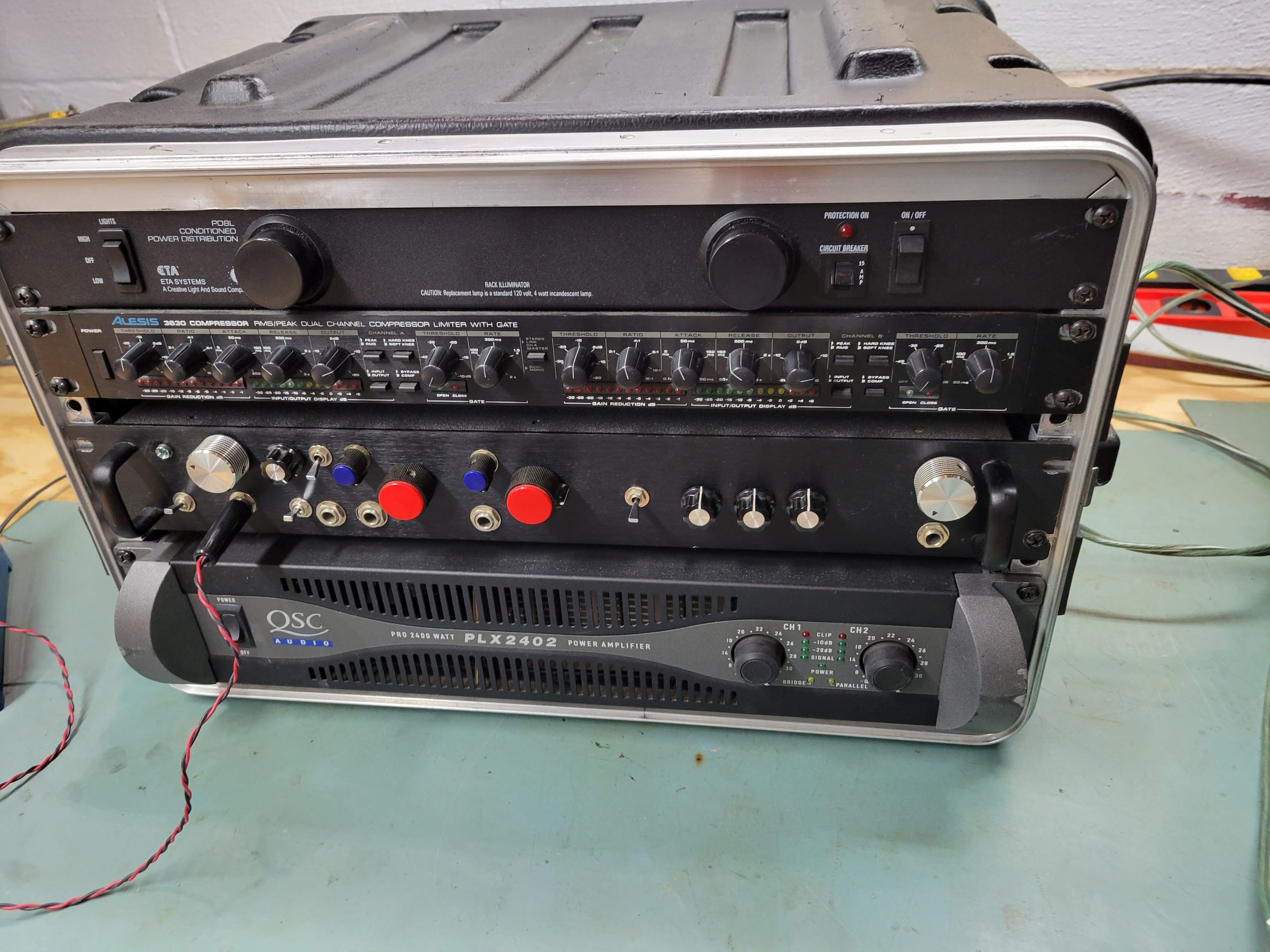
The electronics were designed a long time ago but are still quite solid and an excellent setup for clean tone for bass guitar. There are no fancy circuits in here, and no intention to run this for distortion or overdrive effects. Those sorts of things are intended to add externally.
The general design of the pre-amp is built for 2 mixed effects channels with appropriate gain and buffering for passive or active bass pickups. The boards were built by ExpressPCB back in the day. The sub to high end cabinet crossover is fixed at 200Hz using a 3rd order sallen-key Op-Amp filters.
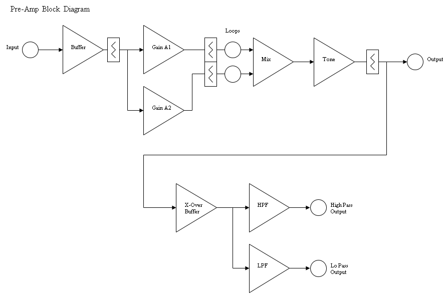
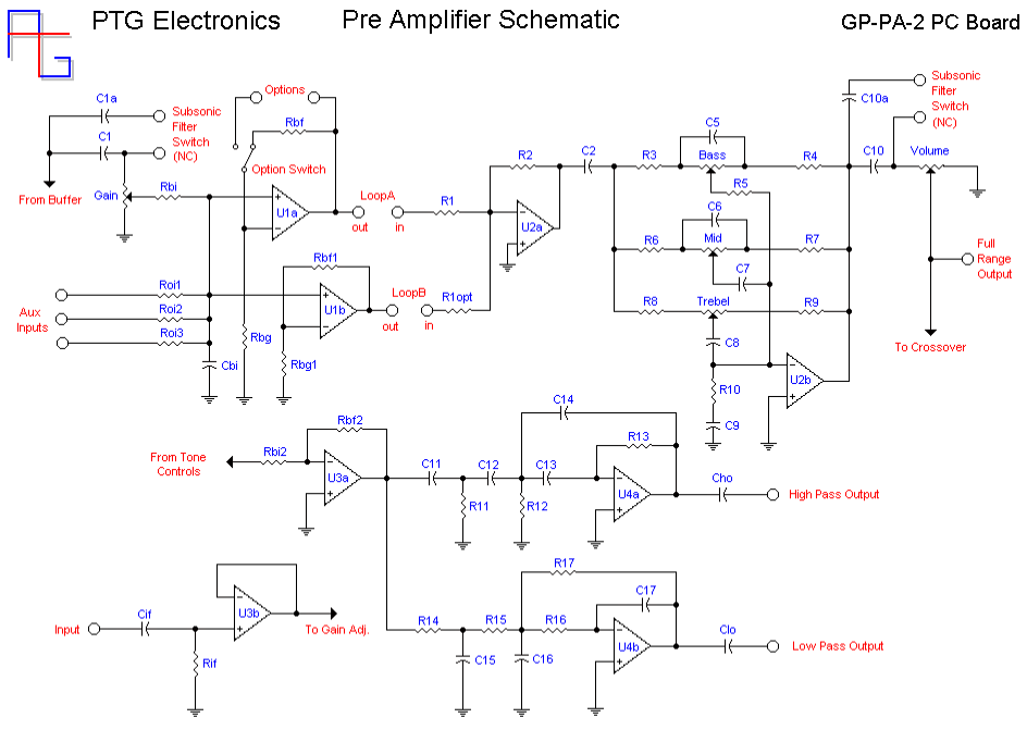
The schematics and an old ExpressPCB board file are downloadable here. In the Parts List Excel file, the component values and selections can be found, with options to modify parameters such as the crossover point and gain throughout the system. This was setup long ago, but I may be persuaded to assist with the selections if you contact me.
Crossover Testing
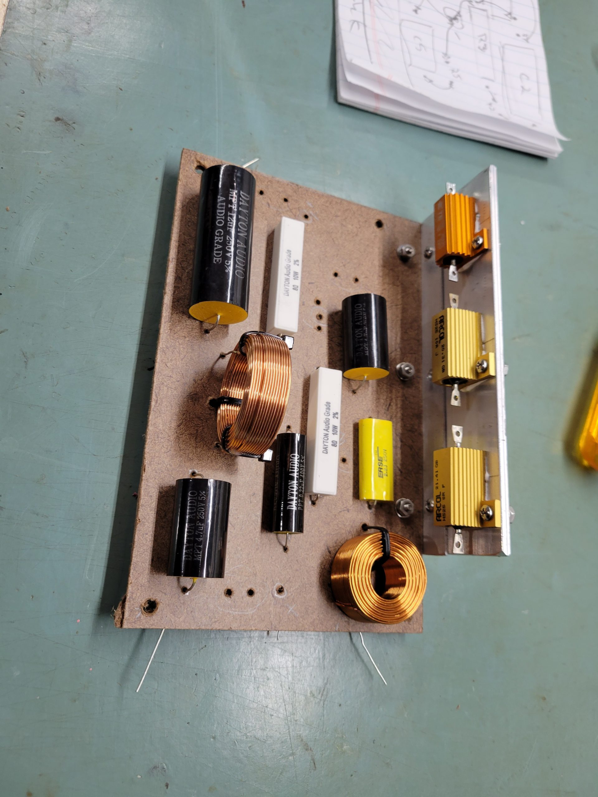
The crossover build was done immediately with point to point soldering, I didn’t do the whole prototype think with clip leads or a temporary build. This was partly driven by time and wanting to get this project done, and the extra complexity of the filter compared to my test lead inventory.

This is a little risky, so the layout was planned carefully and the joints made with great attention to detail to avoid error. With the filter board assembled, a quick sweep with DATS confirmed I had soldered everything correctly and the impedance was closely in line with the simulation. Then it was time to validate with some measurements.
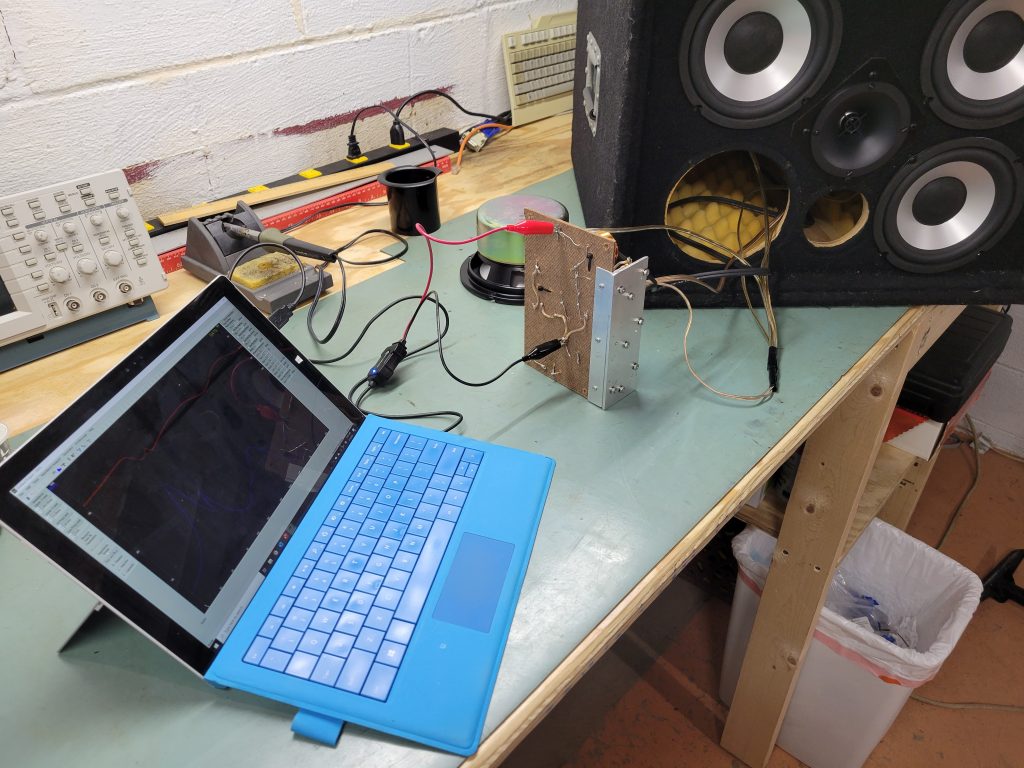
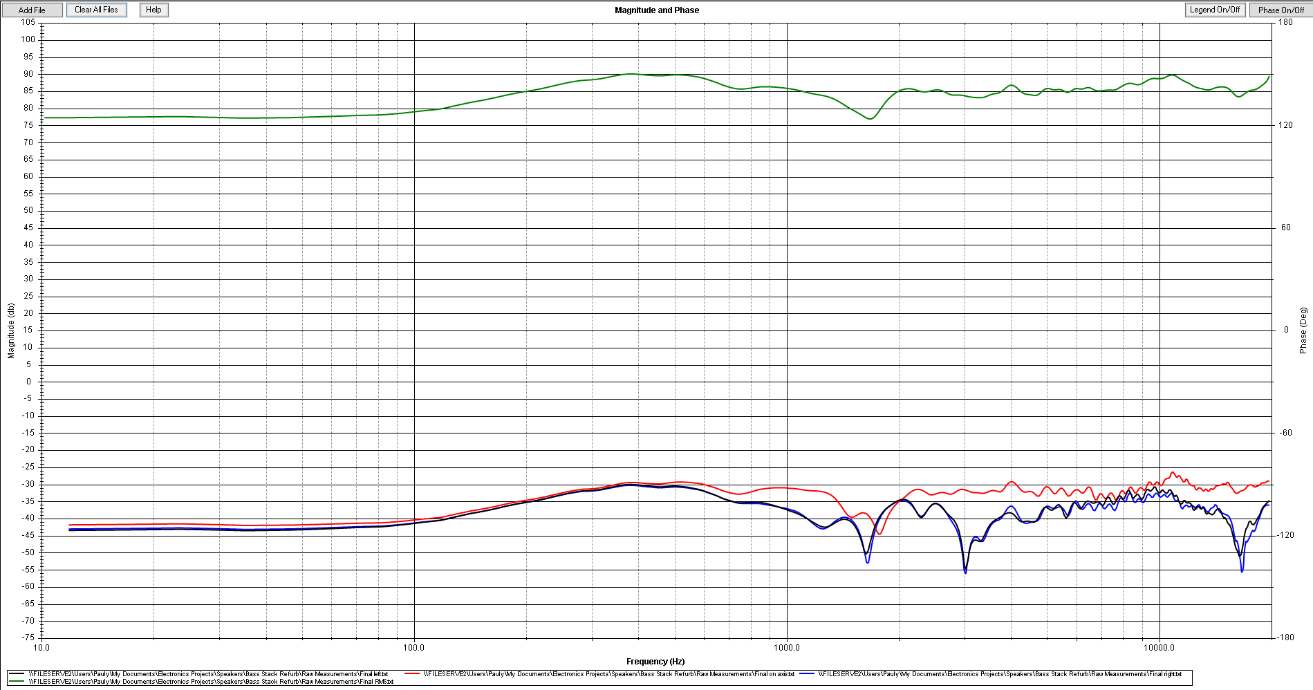
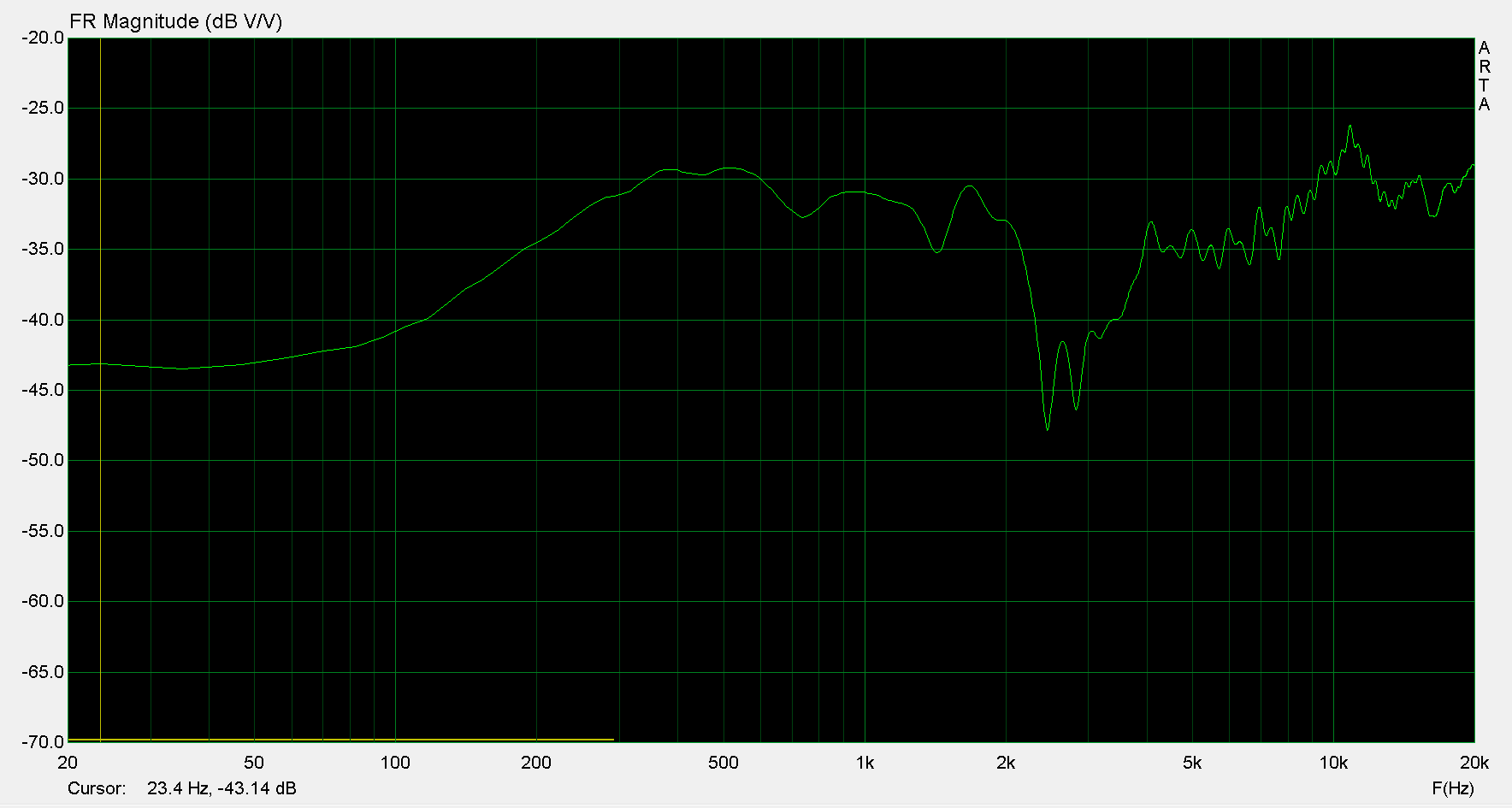
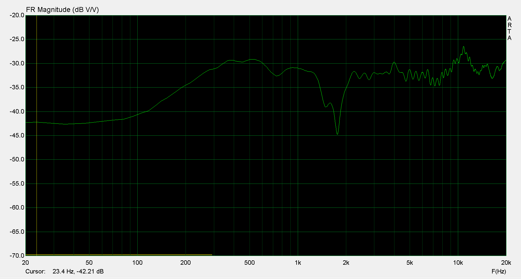
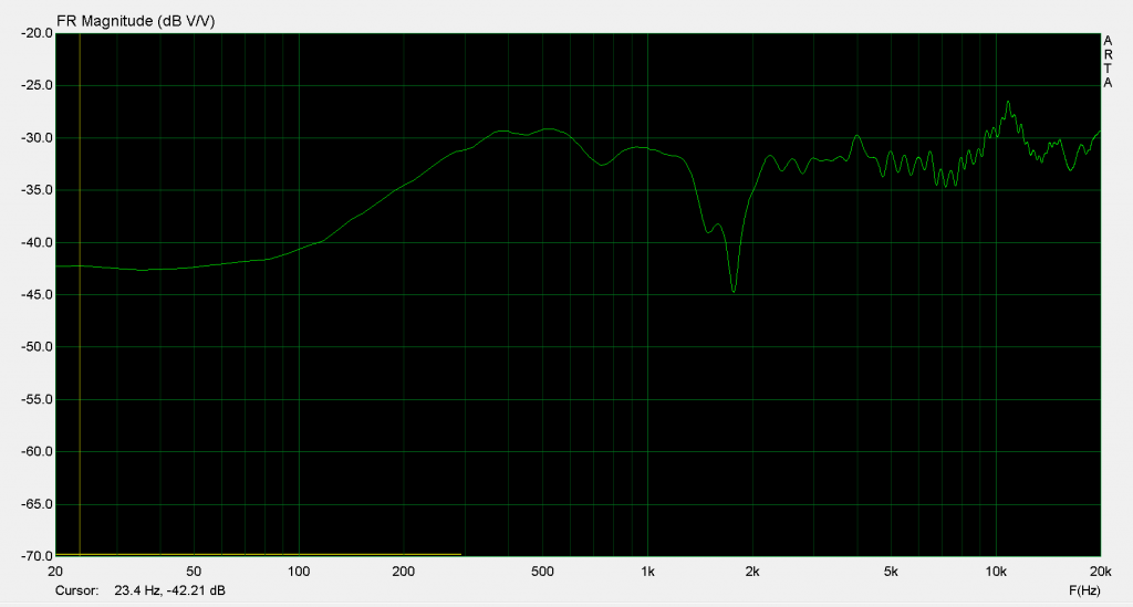
Approximately the same position was used, but the distance to measurement wasn’t locked in exactly. Upon sweeping the system, a null at 2KHz was in there leading me to believe the tweeter was wired reversed. A little de-soldering and soldering swapped that for another sweep. This time, the results were worse, so the tweeter polarity was swapped back again. What is happening was hidden in the comb filtering during filter design, and dependent on the listening distance from the woofer array.
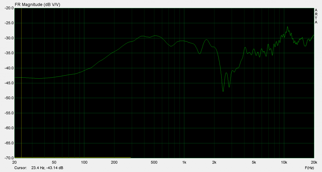
Further validating this measurement, I did another 3 point measurement across the front with an RMS calculation. With that done, the null is much smaller, but additional measurement points asymmetrically across the front and with different distances would really tell you how the frequency response ended up. Generally though, the tonal balance from woofer to tweeter is spot on, and the response is very flat above the comb filtering region.
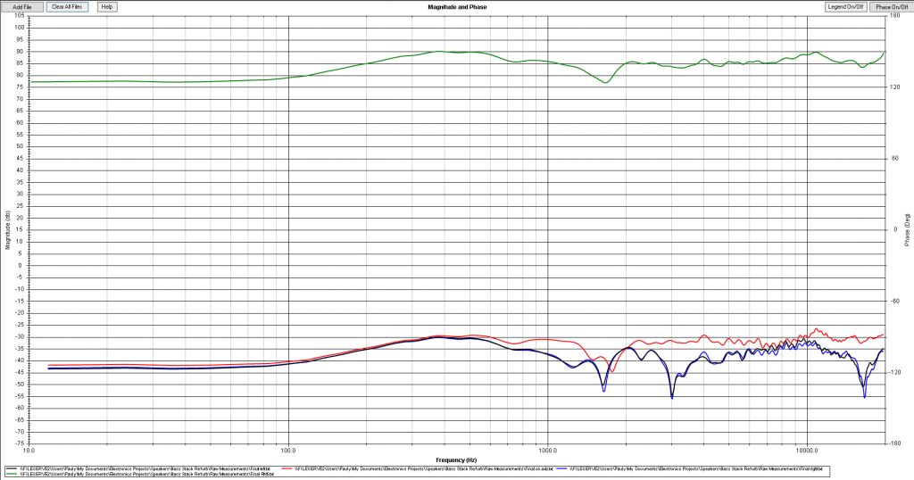
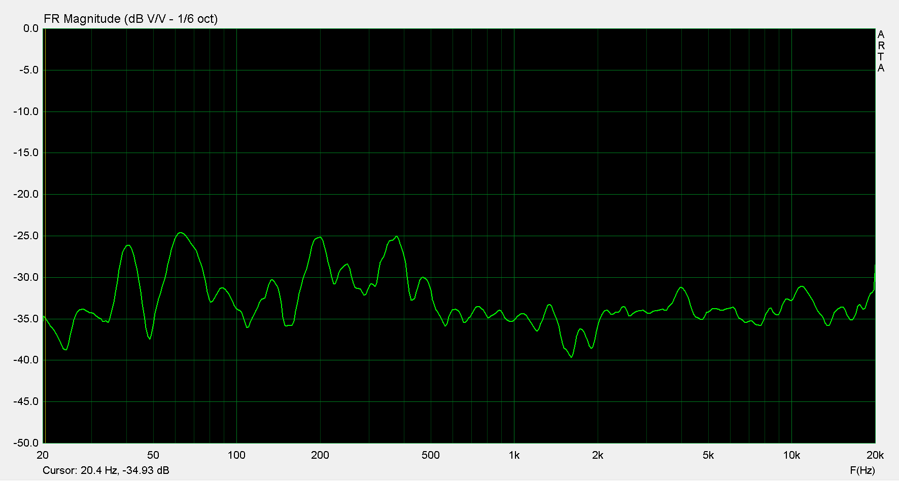
To get the full system, I ran a longer measurement distance and used the sub and high cabinets for an un-gated measurement. The system shows a full range response from 30 to 20kHz with very little null at 2KHz, and a bit of an elevated response below 500Hz by 5dB which is pretty appropriate for bass guitar.
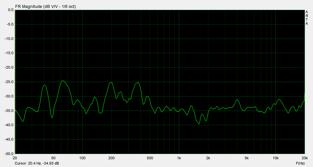
Playing some full range music through the system is acceptable, like a general PA cabinet and far better than any dedicated instrument amplifier let alone one dedicated to bass guitar.
Tips and Tricks
Main lesson learned: Do not array multiple woofers like this for a HiFi speaker build! The resulting comb filtering is difficult to identify and deal with due to the differences between any measurement points in space. There’s good reason you will not find this sort of driver arrangement in HiFi designs or pro audio PA systems. For instrument application however, you see this setup all the time. The aluminum cones and 4 driver array immediately should remind you of a commercial Hartke bass cabinet. Guitar and bass amps are full of 2-8 driver arrays like this and have an uneven frequency response to go with them.
The reason for that is simple, nobody expects fidelity out of one of those cabinets. In fact, they’re typically designed to color the sound as a feature with either frequency response curves and / or distortion. No bass player alive will deny the incredible rock tone from an Ampeg SVT setup with 8 10” woofers in a roadie back killing cabinet. But no matter how many effects you put in your signal chain to change your tone, the resulting output will still be the Ampeg SVT signature tone for the most part.
Using an amplifier that is actually accurate is a bit of an acquired taste, but grants you the flexibility to create the tone yourself with either outboard effects or simply the way you choose to attack the strings.
Conclusion
Given the compromises inherent to the design and the parts and drivers available, this project is considered a total success. I’m back up and running full range with a new tone that is far cleaner and more controllable than before. The cabinets certainly look used, but with a fresh cleaning, new corners and coat of paint they’re ready to rock!
All the Pictures