Anarchies Construction
Moving to reality
Limitations
My available tooling is minimal, really minimal. So doing a complete build from scratch requires some careful planning and extra attention to detail to get everything done correctly. I’ve been using this limited arrangement of tools for years, initially documented in The Art of Do It Yourself Speaker Design back in 2015. I’ll break it down by step for the benefit of anyone with similarly limited tooling.
Raw Material Planning
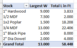
At the risk of exposing more of my OCD than the public needs to know, I used my SketchUp model and broke down each board cut dimension into Excel.
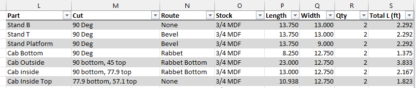
Then each board type could be subtotaled and total board length calculated.
This was my attempt to limit trips to the hardware store, which did work pretty well this time!
MDF Cuts
To get the panel home in a Mazda CX-5, the 4’ x 8’ panel has to be cut down on the store panel saw. I cut it down into a little over 26” strips to accommodate a pair of 4’ long boards of the most common width of 13”. At home all cuts were made with the following set of tools:
- Circular saw (7 ¼” blade, Skillsaw 574 unknown age)
- Aluminum clamp on saw guide
- Bar clamps, small c-clamps
- 6” combination square, tape measure, pencils
This was setup on basic sawhorses, keeping the cut directions so the wood didn’t fall off after the cut was done. This means taking little notches out of the sawhorse 2×4’s. To minimize that, cut depths were kept just past the kerf of the blade through the wood.
The downside of the clamp on guide vs. a table saw is repeatability. I made as long as a cut as possible in each common dimension, but inevitably multiple pieces had to be utilized so each setup had to be individually measured. That introduces tolerances based on the pencil marks and clamp positions that just can’t be avoided and would be much tighter with a table saw and reliable fence.
The combination square really helps out with the guide setup. By using the square for reference measurement, you can pretty quickly offset the guide to the cut.
Miter Angles
For this build, there are 2 additional complications over regular 90 degree butt or rabbet joints. First, I want to hide any lines that may telegraph through the finish at the top, so miter cuts are required to line the seam right at the corner. Second, I’m doing the odd angle on the inside edge that will require calculated miter angles and setup to cut.
SketchUp did the angle calculations for me, so I only had to do some basic adjustments in Excel to make sure I had all the numbers correct.
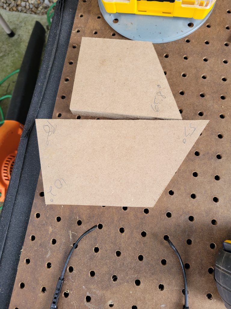
The next trick was setting that old Skillsaw up at those angles. There is no gauge on the saw, and I wouldn’t trust it anyway. I do however have a basic Ryobi miter saw, only an 8 ¼” blade with no sliding, just angle 1 and angle 2 adjustments. The angle adjustment on the miter saw can be measured with a gauge though, adding a tool to the required list of a good protractor or in my case a nice old Starrett angle gauge. I used some scrap MDF and cut the angles into a few inch wide piece to use as setup tools for the Skillsaw. Just align on the bottom plate and flatten the blade against the edge of the reference angle and tighten it down.
With the angle set, the setup of the guide was a little trickier to nail and most of these cuts had to be done individually measured which really risked some tolerance errors. I also found that the deeper the miter angle, the harder time the old Skillsaw had with the cut. My blade was replaced last year, and I didn’t think it had that much time on it but perhaps I’ve underestimated the wear. Regardless, I made it through the cuts and had a pile of MDF matching the drawing.
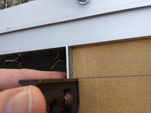
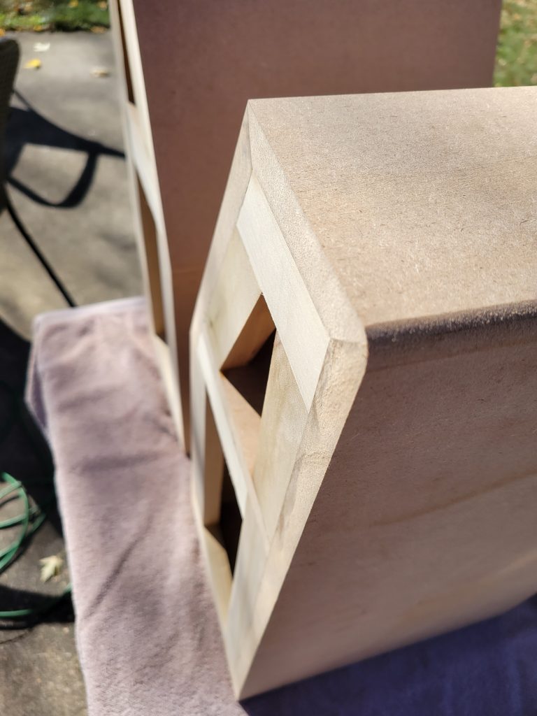
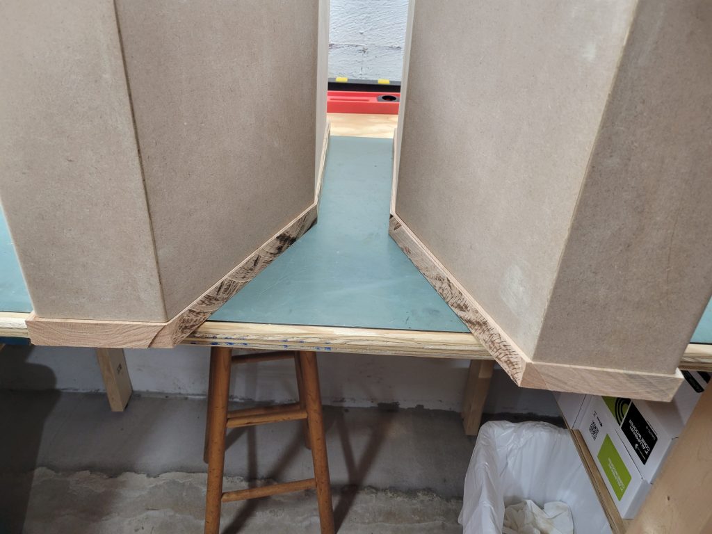
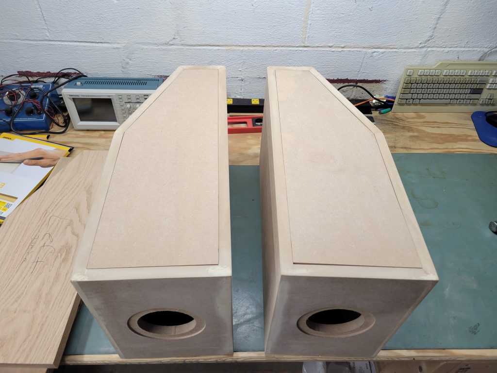
To sanity check my miter cuts, I did a quick tape the edge and stand it up test. Simply line the panels up edge to edge where they mate, use painter tape to hold them together. Then, carefully stand them up on edge and fold in to test the fit.
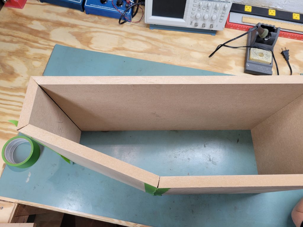
I definitely see the tolerance problems inherent in the cut method I have. This is what DIY is all about, without upgraded tooling or subcontracting out the cuts I’ll instead spend the time on patching and covering these errors. It’s not the perfection of the parts, it’s the end results that count here.
Bottom Edge Rabbet
This one was done with my typical method for 90 degree joints, a simple 3/8” rabbet edge using a router bit. This added another key power tool, the Craftsman hand held plunge router labeled “Super Router” also of unknown age. Combined with a 3/8” rabbet bit, all I have to do is measure and test to ensure the depth is also set to 3/8” and hit the mating edges of the board.
One important tip on hand held edge shaping with a router. If you’re not using a router table, you’ll want a good surface to steady the router while running the edges to ensure you don’t slip and cause a bad angle. I do this by keeping the plate of my Jasper Circle Jig on the router, giving me a nice large surface to keep against the assembly. This adds a step when changing bits but is well worth the security.
Glue Up
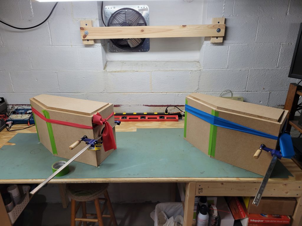
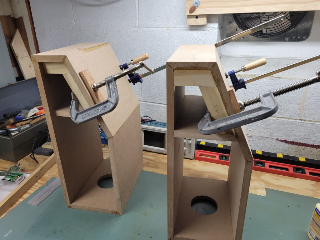
The same painter tape method was used for the glue up. With a healthy bead of Titebond II the miters were put together with as much squeeze as possible, and with attention to making sure they were flat on the table to minimize any errors where the panels match up.
One can never have enough clamps, and in my case I have way too few. I used a single bar clamp across the bottom where I have rabbet joints, and employed a couple exercise tension bands tied around the whole thing to add pressure while the glue dried. I loosely propped the cut back panels in there with the idea that it would help keep the angles correct. That worked more or less successfully.
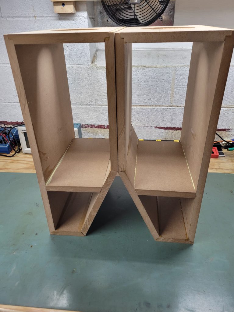
I waited a full 24 hours before messing with them further, the next day bringing the opportunity to drop in the woofer / mid divider panels. These were just dropped in to where the cut landed with gravity doing its job keeping pressure on the glue.
First rework
After another 24 hours for the divider panels to dry into place, A good inspection revealed our first major issue with the construction. The top miter join had come apart on one of the assemblies, not quite enough clamp pressure to keep the joint together.
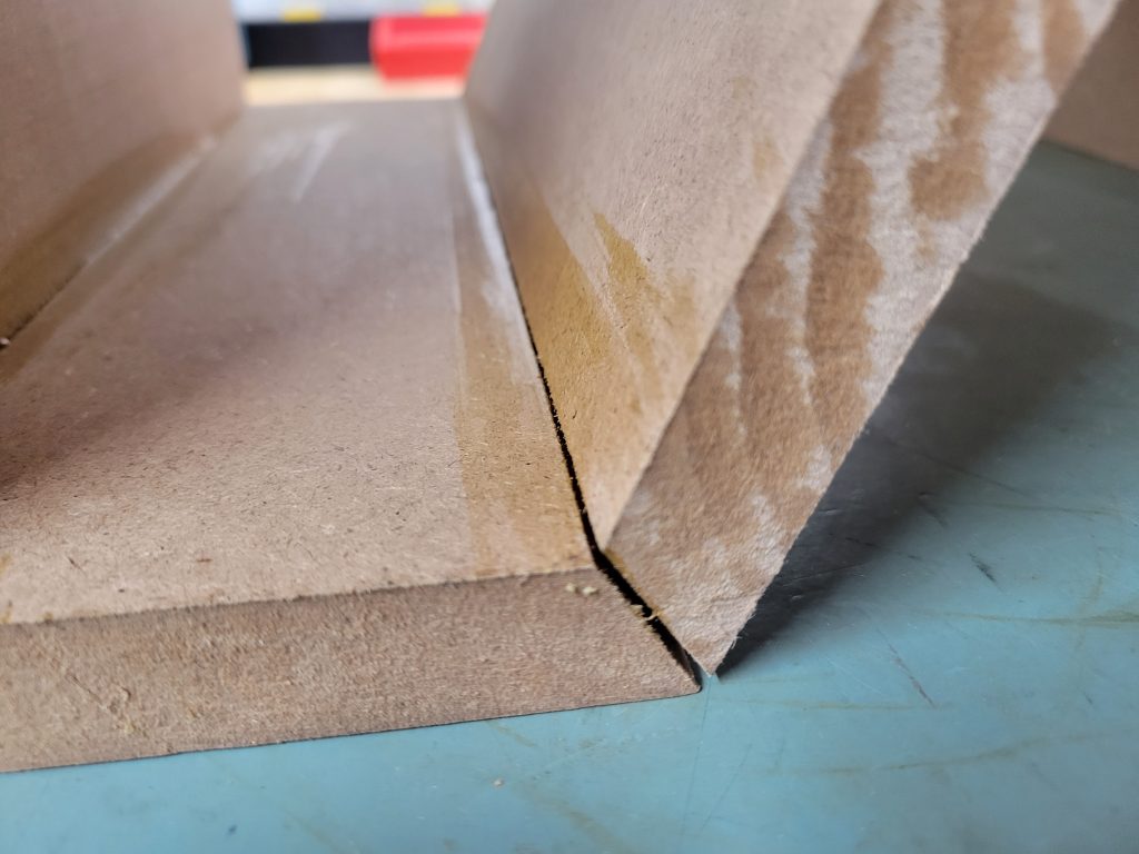
Luckily the whole thing didn’t pop, with only one end coming loose while the other held tight. The challenge now is to re-glue and clamp that down with an odd angle to use. That angle meant that my bar clamps were useless, so in order to create an edge to clamp I used a spare chunk of Poplar 1×2 and a couple wood screws to add the board along the edge. This will give me a couple screw holes to fill in and hide, but that should be an easy cost and this edge joint must be fixed to continue.
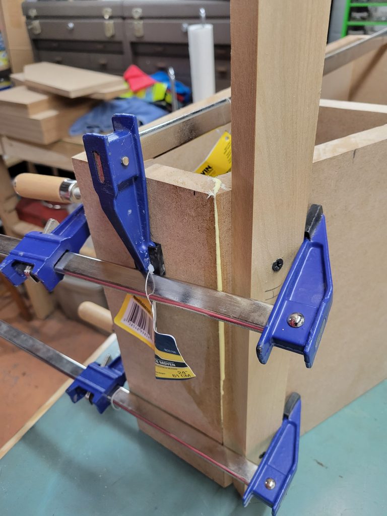
With as much glue as I could get in there and a triple clamp setup that joint was held tight for another full 24 hours. Now I had an MDF frame to work on, and it was time to start adding the poplar 1×2 edges around both sides of each frame.
Frame Miter Cuts
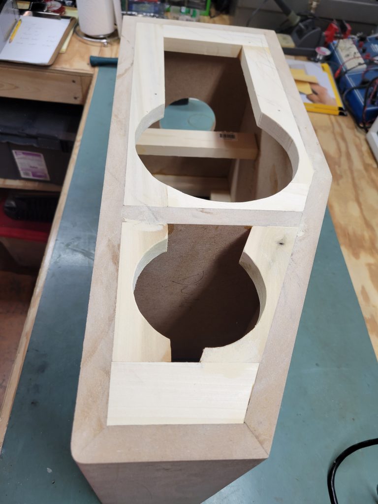
The 1×2 hardwood frame around the inside lip of the MDF enclosure is critical for a couple parts of the design. First, it strengthens the whole thing by bracing the edge very effectively which is extra important when utilizing removable baffle and rear panels. Second, this lip provides the surface area to effectively seal against and the location for threaded inserts that will be used to simplify assembly.
The front lip is to be 100% flush for the baffle board to fit directly against it and seal. The rear lip is to be inset the ¾” depth of the rear MDF panel. This is the start of the differentiation between the right and left speaker, with the angle cut on the inside edge keeping the end location of the tweeters to the outside.
Tooling for this part included:
- Ryobi 8 ¼” miter saw
- 12” Dial Caliper
- Combination square, angle gauge and tape measure
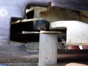
The caliper is quite necessary in this case. Since all cuts and the frame assembly are done by hand, none of the calculated SketchUp dimensions are quite good enough in reality to make tight fitting cuts. Instead, the calipers were deployed for each cut to get them as close as possible.
The other limitation that dragged this process out was a simple lack of clamps. I setup enough clamps to do 4 of the boards at a time. So twice a day, these boards would be cut, lined up, glued and clamped until all edges were covered. The rear inset was gauged using the trusty combination square.
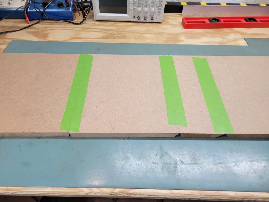
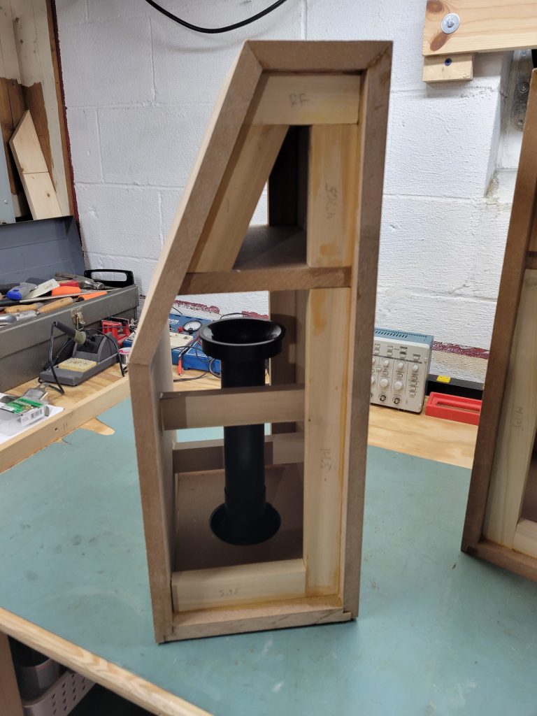
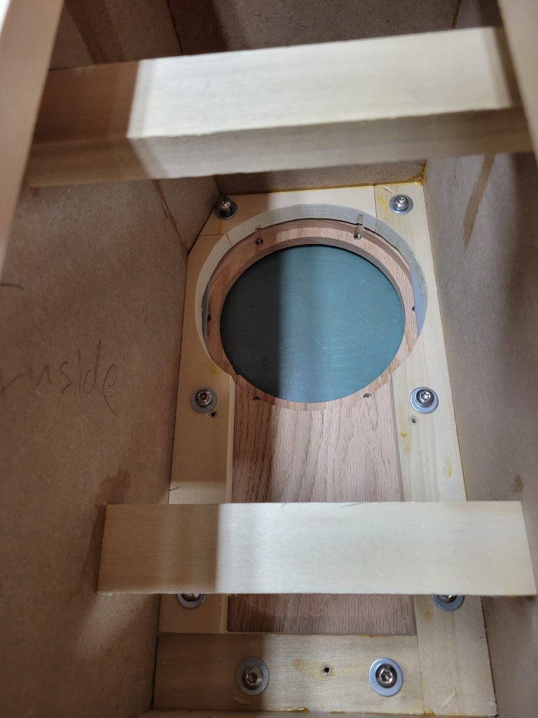
Woofer Bracing
One thing that DIY folks do that is not as common in commercial speakers due to cost is extensive bracing. I’ve never really done as heavy bracing as some others, and this is probably no exception. Since my baffle and rear panel are designed to be removable, a full window brace that connects all panels solid isn’t really possible. Instead I’ve focused on the largest side panels, and have opted to use 1×2 stock to connect them rather than a cut out MDF panel. This will provide the vast majority of the bracing strength without a lot of lost volume and easier wood cuts. The braces were mitered to just the right size to squeeze in there. After temporarily pushing in the Precision Ports to ensure I had clearance around the bracing, I used just a little Titebond on the ends and just pressed the braces in to dry.
Sanding
With all the bits glued up and solid, it was time to start flattening out the outside and covering up any errors. For this one more power tool was pulled in, a relatively recent Skill brand hand held belt sander with a 3” x 18” belt. I used a 150 grit belt to process, straightening out the miters and softening the corners just a bit.
The only router edge on the frame is a single ½” round over on the one 90 degree edge on the top. Similar to the rabbet bit work, a simple setup and test of the router bit had to be done, then a quick hit of the top edge.
The front and back surfaces suffered from a little mis-alignment during glue up, particularly on one of the speakers. For now, I flattened them as best as possible using the belt sander. The same was applied to the rabbet joint on the bottom. That 3/8” will always be just a little off as ¾” MDF is not really ¾” thick exactly, so there will always be a little tolerance to clean up when doing assembly that way.
After a first pass of sanding, I used some Plastic Wood to fill in any seam gaps all the way around. A few trips back and forth from sanding to filling and the frames were in good shape.
Baffles
With the frames all set, it was time to select and process the baffle. A trip to the nearby specialty wood shop was in order. I ended up pretty overwhelmed with the selection available at Woodwerks Supply in Columbus OH, so it became a search for the best appropriate width 5/4 board I could find. The main goal being just over 9” wide and long enough to create 3 baffle boards just in case I mess one up in the process.
I ended up with a red oak board, no idea why. Upon getting it home I realized that both my floors and kitchen cabinets are red oak, so perhaps it was subconsciously chosen. Regardless, I don’t want the speakers to look like my kitchen cabinets so some creative stain and finish will be in order later.
The first step was to cut them close to the correct dimension to minimize how much had to be cleaned up with a flush trim router bit. A simple pencil trace around the cabinet and some rough cuts with the miter and skill saw and I was close enough.
To hold the baffle boards in place for processing, I just used a couple wood screws through the internal framing and into the baffle. The holes won’t be needed later and will end up invisible to the finished product so no big whoop.
Normally in past projects I’ve been pretty abusive with my router bits. I’ve tended to make big cuts in single passes through MDF or poplar even ¾” thick. This time, with a 5/4 red oak board that measures just over 1” thick I’m intent on not destroying any tools. I purchased an improved spiral cut flush trim bit with a bottom bearing to use, the main downside being that with only a ¼” shank router option my cut depth is limited to 1”. Me and the hardware helper man thought we could make it work.
In reality though, that little bit of extra wood depth did complicate things a bit. The router bit didn’t quite cover the depth, leaving a tiny lip at either end that limited my cut to only about 1/16” before it would bottom out in the non-cutting portion of the bit. The fix to that was to simply take small cuts, moving the bit to the top and bottom of the board alternatively until I reached the bearing and got a nice smooth pass all the way around.
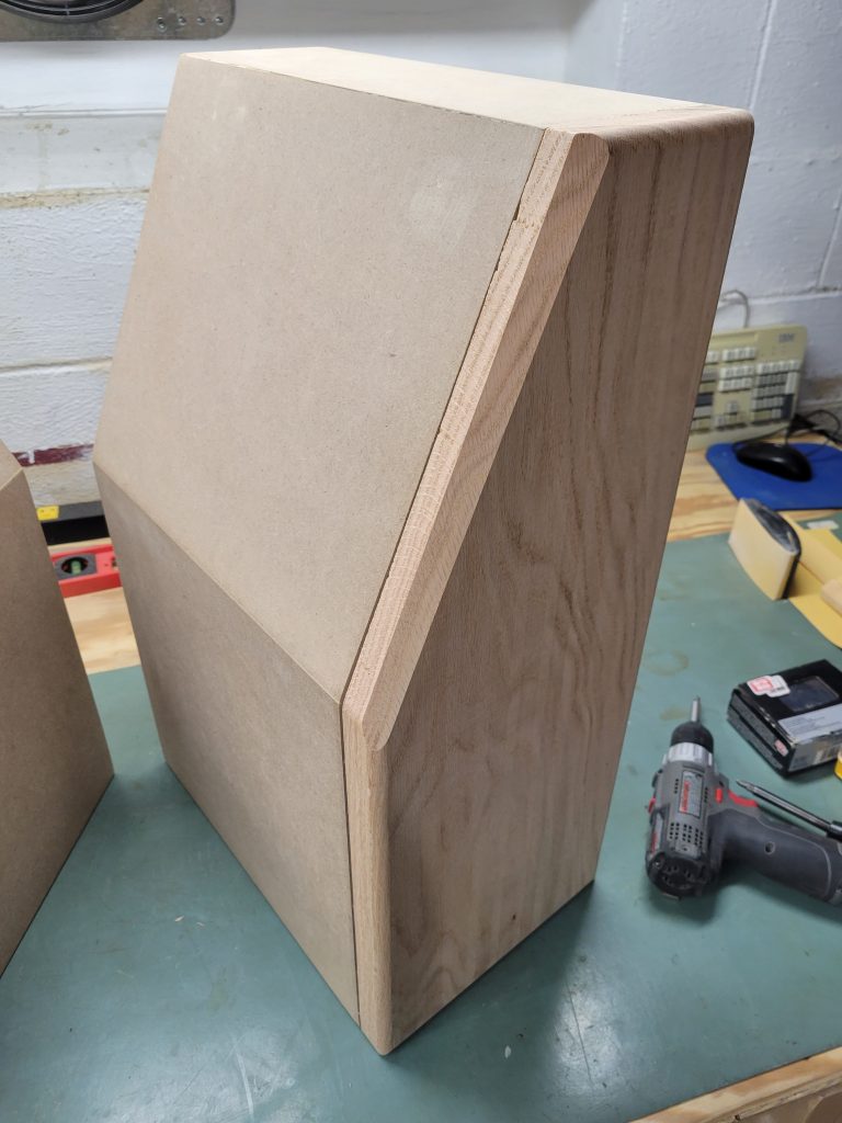
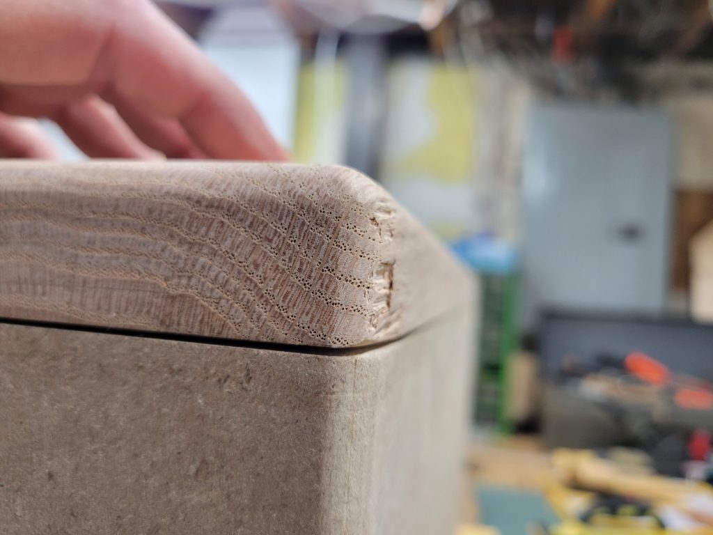
A bit of minor tear out happened while passing around the baffle, not awesome but not a deal breaker. This will be a bit of evidence that these are entirely hand made in the end.
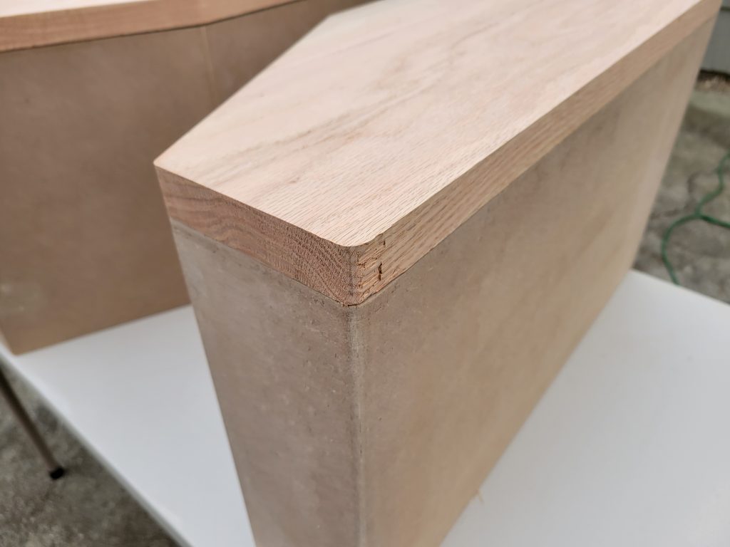
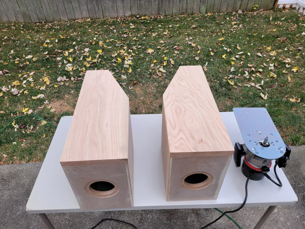
With the flush trims done, it was time to form the edges as planned. A ½” roundover goes all the way around with the exception of that angle edge. That edge instead gets a 45 degree chamfer cut as deeply as I can set it with my hand held router.
Deeper round overs and edge treatments are better for managing diffraction on a speaker, but with my ¼” shank router I’m using the largest bits that fit so I’ll chalk that up to a tooling limitation and run with it.
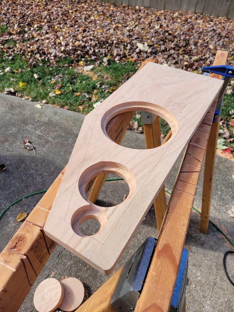
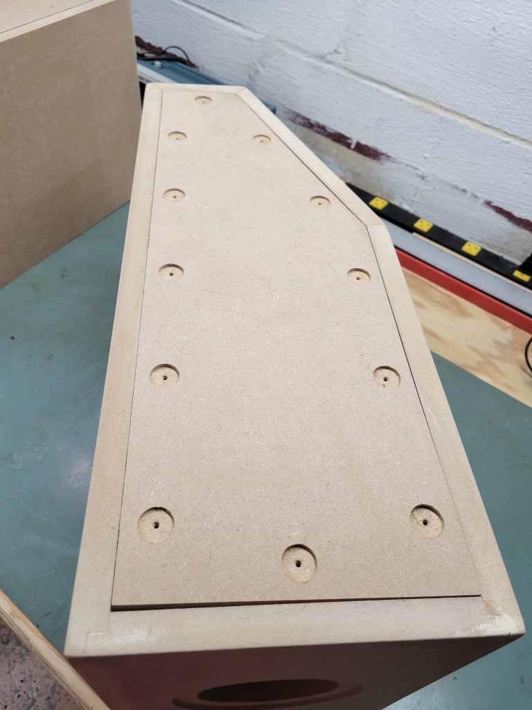
Speaker Hole Machining
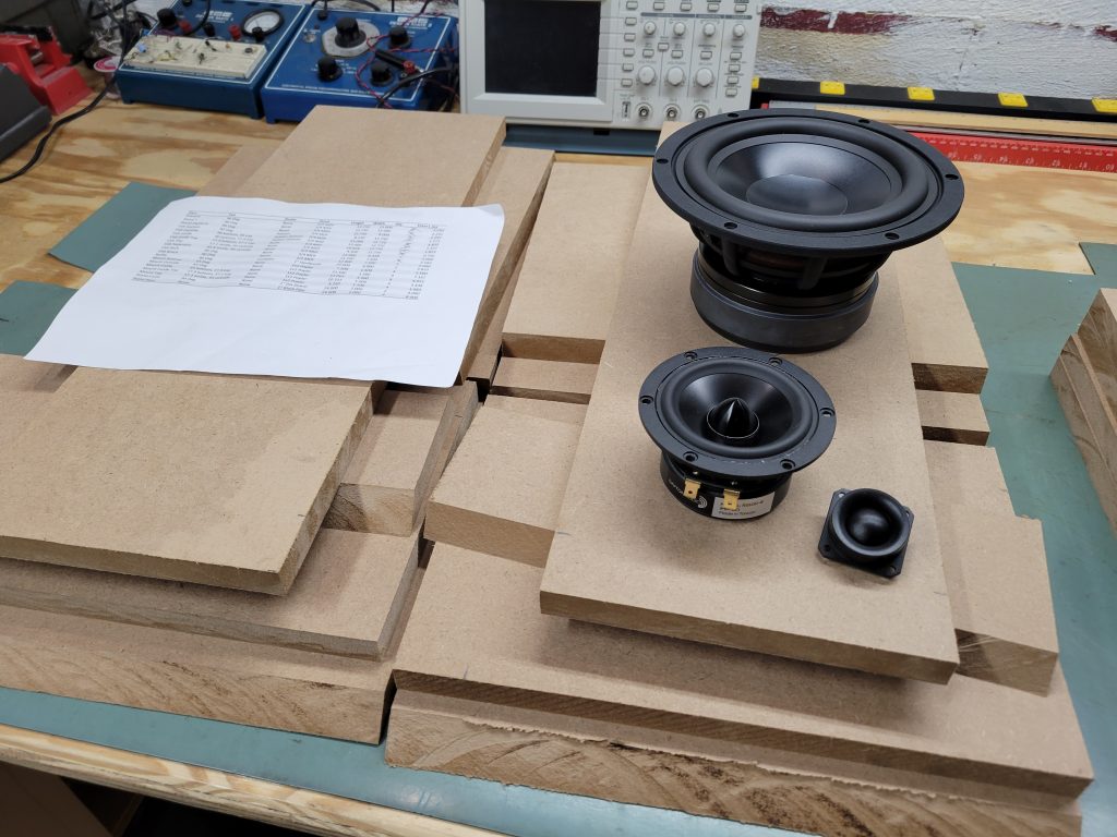
The driver layout was measured to be along the centerline of the cabinet with the angle. The woofer ends up below the angle a touch and centered as well leaving enough distance between the mid and woofer for the divider panel and a good inch of mating surface to seal against.
The holes were all measured, and the Jasper Circle Jig was utilized to cut the recess using a ¾” flat router bit. The jig is not marked for a ¾” bit, so this part has to be hand measured using the calipers and tested against the actual drivers for fit.
Once the recess is cut, the driver hole can be cut. This time, also in the interest of not destroying a new ¼” straight bit I did the cut in 2 passes about ½” deep.
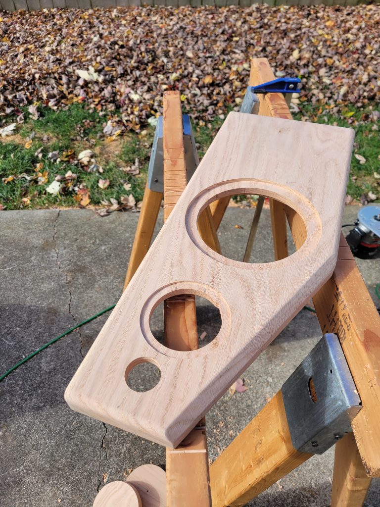
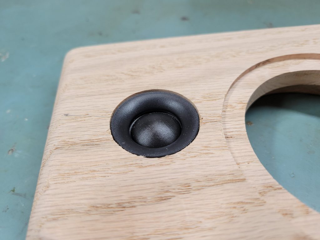
The tweeter hole is too small for the Jasper jig, so that one is cut with a 1 ¼” Forstner bit. That ends up slightly small for the tweeter, so a drill attached sanding disk was used to widen the hole until the tweeter fit snugly.
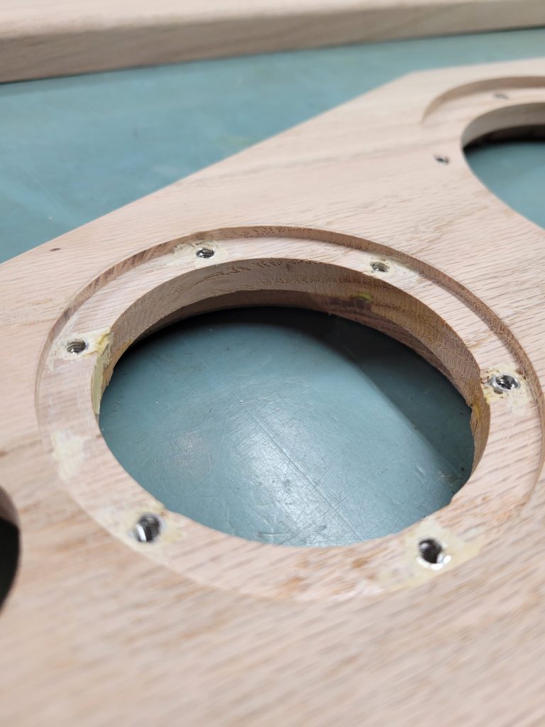
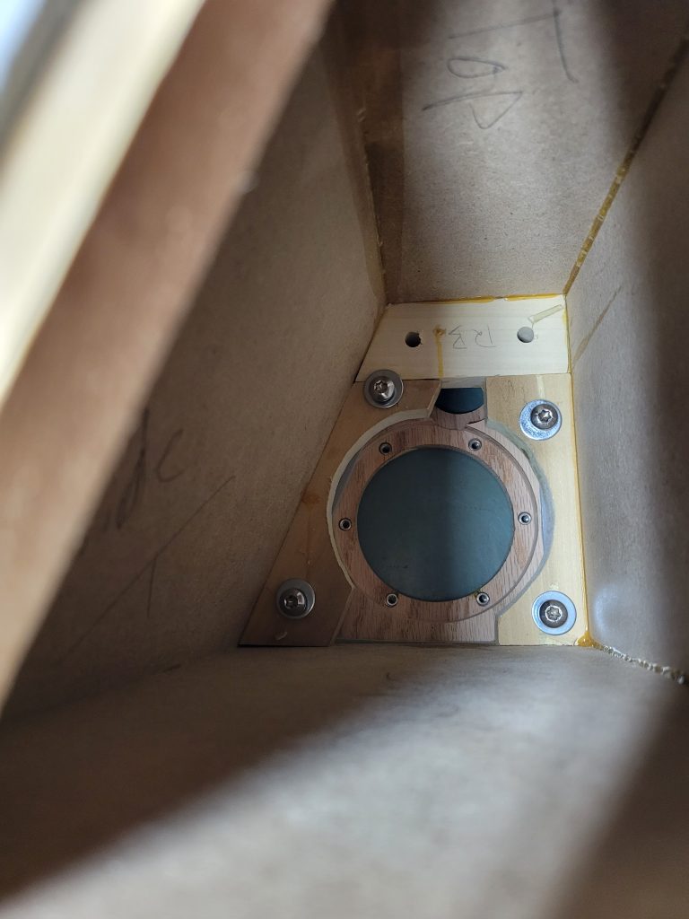
For the back of the baffle, it’s important to ensure the speaker drivers have enough air space to breath properly inside the cabinet. Too much restriction there can alter performance and cause some response problems. With a baffle board over 1” thick this is particularly important for this build. Typically, folks will use a chamfer bit and scallop out the wood leaving thickness only at the screw locations. In my case, I’ve opted to thin the whole board down to 3/8” thick at the speaker mount locations. I’m relying on a couple things for this to work well, first this is oak so I don’t have to worry about the strength at only 3/8” thick. Second, I’m planning to use 8-32 stainless threaded inserts to bolt down the speakers and chose the thickness to match the fasteners.
To thin the wood, I utilized the calipers to measure the extra thickness of the wood and subtract out the remaining 3/8”. I used my 3/8” rabbet bit and set the depth for each hole to match. The woofer and mid get a 3/8” thick mount, while the tweeter was measured to leave ½” remaining to land flush in the front.
And the fit test…
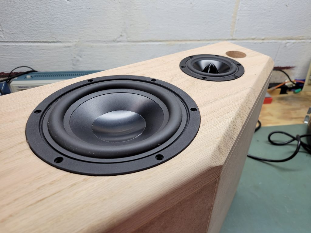
If anything, I wasn’t quite deep enough on the driver recesses for the mid and woofer. In prior projects, those really didn’t fit in until the drivers were bolted down tight, so I’m hoping that will happen a little. This is really hard wood though, so the drivers may end up slightly proud in the end. The tiny bit of lip will raise the frequency of any ill effects really quite high based on the actual lip vs. the wavelength of the sound, so I’m hoping for the best.
Rear Panel Fit
Since the assembly was hand made and the back panels were cut to the drawing, there was a bit of a disconnect between the angles that kept the panels from dropping into place. This required some hand held sanding to take down material a little at a time to get them to fit. The belt sander was able to get these down to size with the only issue being the lack of a lot of control on how square everything ended up. Ultimately, there are some gaps around the lip that will add to the hand made vibes of the speaker, but not look so bad and definitely not cause a functional problem.
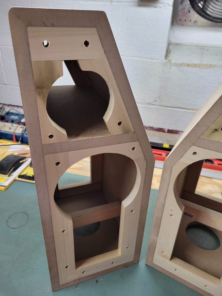
Frame Touch Up
The baffles now cut out gave me a guide for the driver holes to cut out the internal 1×2 frame to accommodate. A little pencil drawing and another power tool was required, an old Craftsman jig saw. That simply followed the pencil lines, clearing the way for the drivers to be assembled.
With the frames and baffles ready to assemble, a careful inspection of the flatness of the mating surface was needed. This part is critical for the final assembly, the speaker must be very well sealed to work properly, and definitely not leak between the woofer and midrange chambers. I had a leakage issue with the assembly of the Shia LeBoom Bluetooth speaker that ultimately dropped the efficiency of the passive radiators in the box. While that still works OK, I’m adamant that doesn’t happen with this build and I get and maintain a perfect seal as if the box was hard glued together in the end.
The fronts were sanded flat with the belt sander, which looked great on inspection but didn’t quite hold up when the full baffle board was laid out on the surface.
A gap of about 1/16” was observable around the frame, with some rocking back and forth following the high / low areas of the frame. This needed to be brought down to within perhaps a 32nd or so in order to allow thin weather stripping to create the seal needed. The best method to flatten a whole assembly like that is to sand the whole thing at one time. Alternatively, if I had the tooling a large format belt sander, table saw or a CNC router would have done the trick. In my case though, I utilized the extra red oak board I had on hand and glued 4 sheets of 100 grit paper to it. That gave me a large sanding surface that would hit the whole frame at the same time.
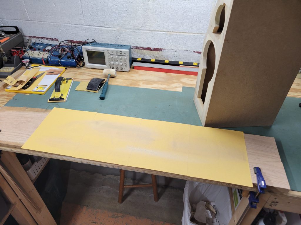
With the sanding board clamped down, all I had to do was drag the assembled frame across the paper when I had a few minutes here and there. Throughout the week I continued to flatten the boxes little by little until they were acceptably flat and I was comfortable with the seal potential.
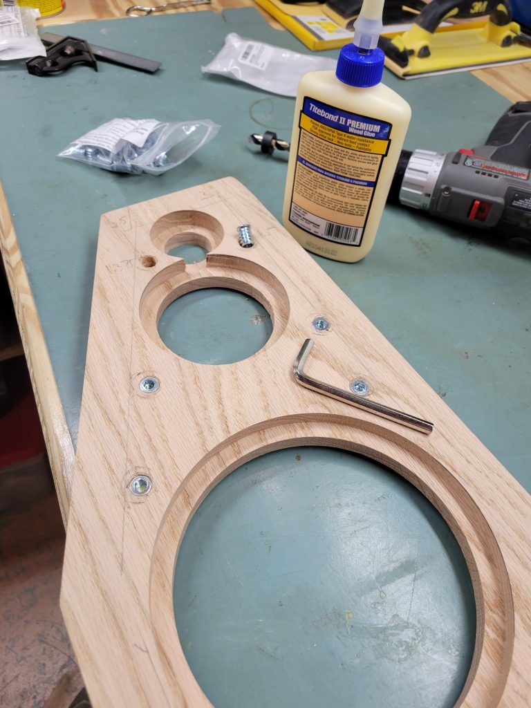
Hardware Installation
A few deliveries later, I had a whole pile of hardware chosen to assemble the cabinets.
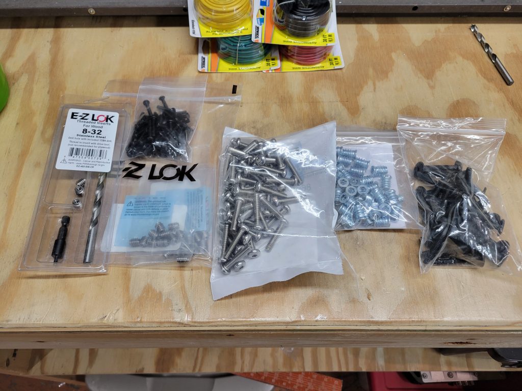
The hardware selection is important to me, I prefer black anodized for anything exposed on the outside of the cabinet. I also require small heads for minimal exposure on the driver screws. For the front and back panels, the screws needed to be meaty enough to be strong. All were planned to use threaded inserts to ease installation a bit and allow assembly, disassembly, and reassembly without any negative effects such as stripping out wood screws. I landed on the following:
- E-Z Lock 8-32 stainless threaded inserts for the drivers
- 8-32 hex drive anodized black screws for the drivers
- 10-32 Torx head screws for the inside baffle mounts (allows use of ratchet due to the small space)
- 10-32 black anodized hex drive and flat head furniture screws for the rear panels
- 10-32 threaded inserts for all front / back panel mounts
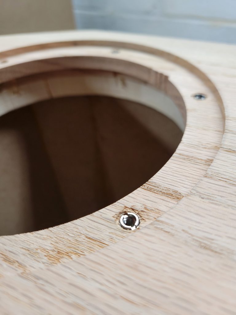
The E-Z lock inserts were the most expensive, and I purchased the installation tool to go with them in order to maximize the success rate of getting those things into the oak baffle. The stainless were required due to the hardwood as well, and the kit comes with a handy tool for the screwdriver and the appropriate drill bit to get them in there. This still proved difficult, as the steel inserts were actually a bit harder than the tool, resulting in the first tool getting rounded off and destroyed before I could finish everything. These have to be done slowly and carefully to ensure the tool stays safe. All inserts went in, and the tiny lip of the midrange was the only potential challenge for the finished assembly.
I mitigated a bit of the potential seal loss by applying some wood filler to the lip and made sure to use some wood glue when inserting and again to reinforce the wood that did start splitting out just a little on the inside. The red oak proved as hard as it should be, and the inserts appear to be plenty strong. A little hand sanding with a block flattened the lip better and should provide a good seal surface. This also left a bunch of wood filler in the nut, which was easily cleaned out using a standard 8-32 tap.
These were not problems for the woofer mounts, the lip there was significantly wider and allowed better clearance for the mounts and a seal.
There’s one rather large gap in my tooling for all of these threaded inserts, all of these holes are drilled by hand due to the lack of a drill press. That leaves a couple things poorly controlled: how accurately perpendicular I can make a hole, and how deep to stop.
For depth, a set of set screw drill stops takes care of that. For the perpendicular though, I simply had to do my best by hand. In as many cases as possible, I used a small pilot hole to ensure the panel holes lined up. That was particularly useful on the back panels.
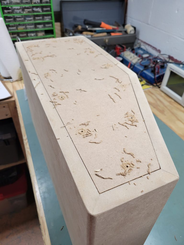
The order of operation to ensure aligned holes and a centered counter sink was:
- Drill small pilot hole
- Use ¾” Forstner bit for the counter sink
- Ream out the panel hole and the threaded insert hole using the appropriate bit
The back panel inserts were installed using the included allen wrench and a touch of Titebond in the hole when locking down.
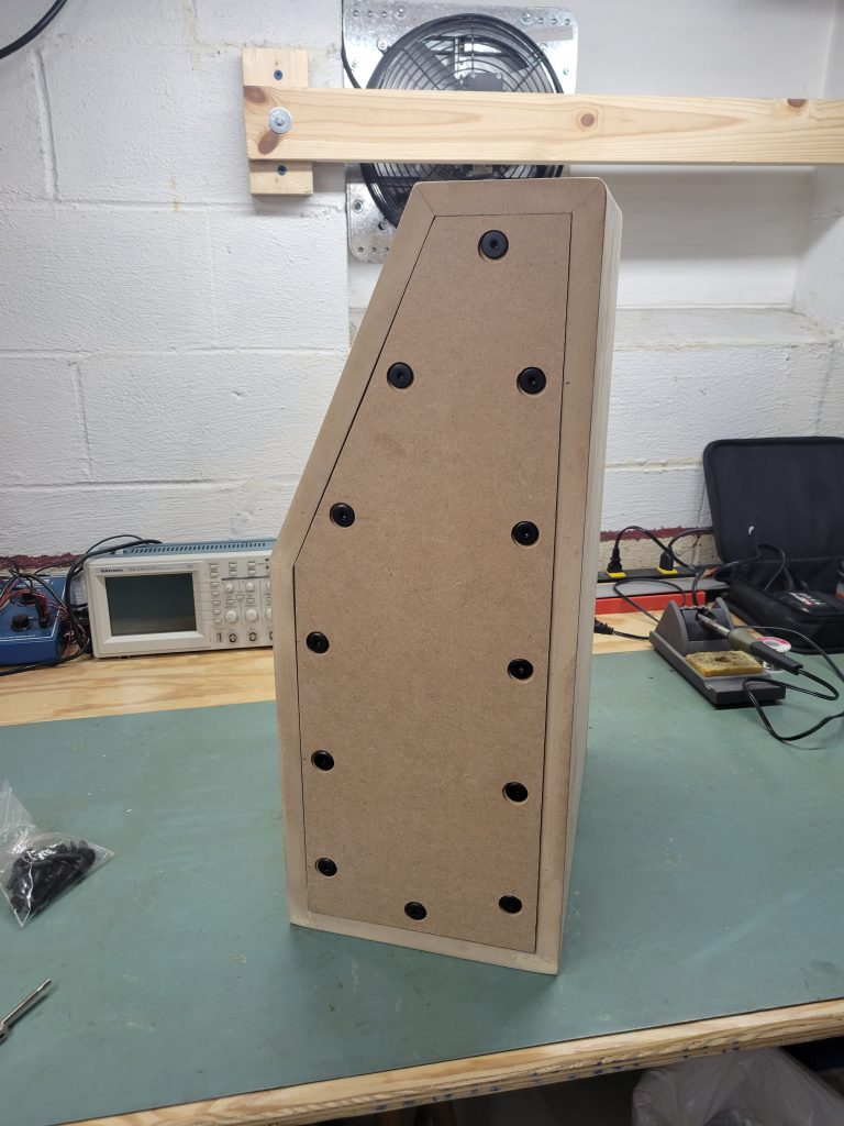
Baffle Mounts
The removable baffle in this case is really solving a single potential problem: avoiding cracks and problems due to the dissimilar woods and different expansion / contraction with temperature and humidity. Hard gluing wood together like that can really shorten the lifespan of the cabinet, but by using fasteners with a little slop in the mounting points the wood can breath a little without cracking. In practical reality, the assembly and removal of these baffles will be very difficult once assembled and stuffed / lined so these will likely be built and forgotten about once assembled.
To get the hardware locations, I simply measured and drilled into the front lip from the outside, then marked the locations on the back of the baffle boards. This is less accurate than doing a single pilot hole, but that was impossible due to the tight fit in the frame that keeps a drill out of there. The internal holes are not critical and need to be oversized enough to accommodate some alignment adjustment anyway. A decent size ¼” washer will be added to make sure the screws are getting enough support to tighten down.
I made one mistake on the placement, the top 2 screw holes were not compared against the back of the baffle and landed right in the recess for the back of the tweeter. A few measurements and a couple holes later that was resolved. Now I have a couple extra holes in the lip that will be invisible in the end, whoops!
The baffle inserts were drilled with a depth stop, and the inserts installed with the same allen wrench and a touch of glue.
Assembly Test
With all the hardware installed it was time to put one together for the next phase of the build process. This proved much harder than anticipated due to the hidden baffle hardware. The openings in the cabinet are simply a bit small for my hands and arms to get in there effectively. This led to some minor bruising on the arm squeezing things in there and the occasional explicative.
I also ran into difficulties with the hardware stemming from 2 issues:
- Poor alignment from internal holes to the threaded inserts
- Glue stuck in the threaded inserts
The poor alignment was easy enough to identify, and a little harder to correct. For that I eyeballed where the holes were not aligned, marked which way they had to move, and finally reamed out the holes with the hand drill a bit to get better clearance.
I actually didn’t notice the glue problem in the process until a couple passes, but once I did it was easy enough to clear using a drill and tap set matching the ¼ x 20 threads (add another tool!).
The woofer side mounts were simpler, but still required some finger contortions to drop the bolts in due to the bracing.
The mid chamber was tricker with the small opening to access the hardware. I also had to remove and install an extra time to get the tweeter in there and wired.
Before bolting up for test, I added wide weatherstripping to the mating surfaces to make the seal effective.
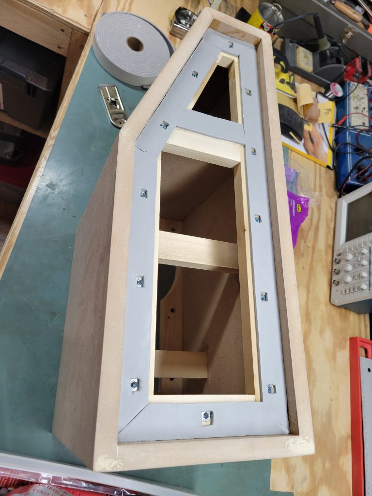
The gasketing is simply applied and cut with a straight razor blade in hopes of minimizing any gaps and allowing a complete seal. For test, this was kept rather simple as this weatherstripping will be removed and thrown out when it comes to the paint and finish part.
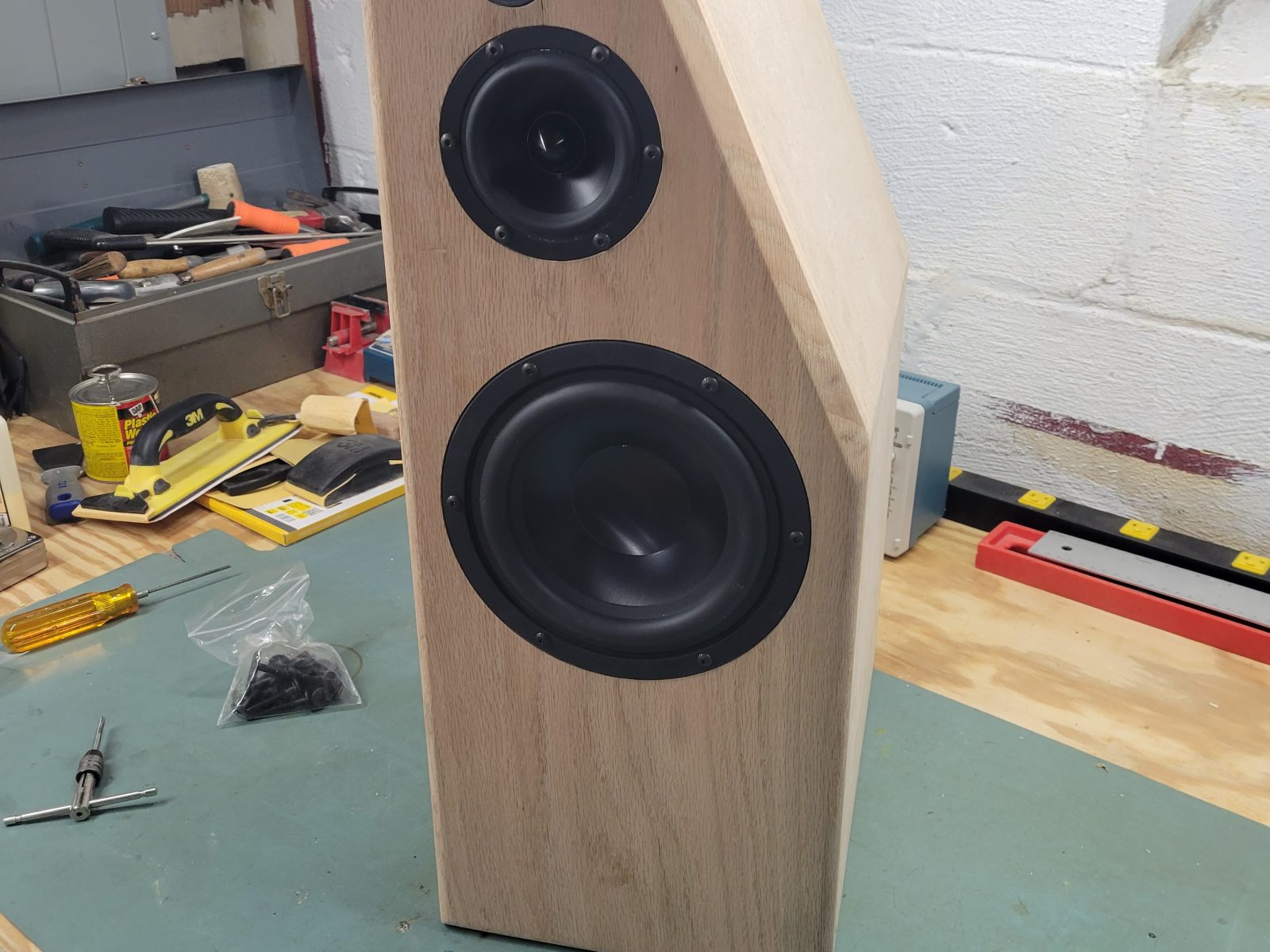
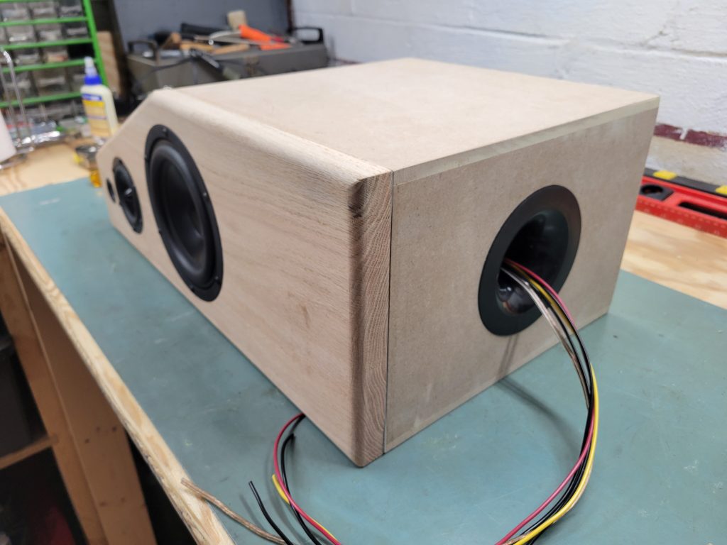
Ready for Test
Now we have 1 of the 2 speakers all sealed up, wired, and ready to start testing.
Up next… Crossover Design.
Pingback: Anarchies – 3 Way Speaker Design Concept | The World of Wogg
Pingback: Anarchies Finishing, Round 1 | The World of Wogg